Chapter 9. Resource-Constrained Activities
A Resource-Constrained Activity is an activity that requires certain resources for being executed. Such an activity can only be started when the required resources are available and can be allocated to it.
At any point in time, a resource required for performing an activity may be available or not. A resource is not available, for instance, when it is busy or when it is out of order.
Resources are objects of a certain type. The resource objects of an activity include its performer, as expressed in the diagram shown in Figure 9-1. While in a conceptual model, describing a real-world system, a performer is required for any activity, a simulation design model may abstract away from the performer of an activity.
For instance, a consultation activity may require a
consultant and a room. Such resource cardinality constraints are
defined at the type level. When defining the activity type
Consultation, these resource cardinality constraints are
defined in the form of two mandatory associations with the object types
Consultant and Room such that both associations'
ends have the multiplicity 1 ("exactly one"). Then, in a simulation run, a
new Consultation activity can only be started, when both a
Consultant object and a Room object are
available.
In an OE Class Diagram, an object type that has a resource status attribute and is the range of both a Resource Role and a Resource Pool property can be viewed as a resource type.
Activity Networks (ANs) extend OEGs by adding activity nodes (in the form of rectangles with rounded corners) and Resource-Dependent Activity Scheduling (RDAS) arrows.
For all types of resource-constrained activities, or, more precisely, for all activity nodes of an AN, a simulator can automatically collect the following statistics:
- Throughput statistics: the numbers of enqueued and dequeued planned activities, and the numbers of started and completed activities.
- Queue length statistics: the average and maximum length of its queue of planned activities.
- Cycle time statistics: the minimum, average and maximum cycle time, which is the sum of the waiting time and the activity duration.
- Resource utilization statistics: the percentage of time each resource object involved is busy with an activity of that type.
In addition, a simulator can automatically collect the percentage of time each resource object involved is idle or out-of-order.

For modeling resource-constrained activities, we need to define their types. As can be seen in Figure 9-2, a resource-constrained activity type is composed of
- a set of properties and a set of operations, as any entity type,
- a set of resource roles, each one having the form of a reference property with a name, an object type as range, and a multiplicity that may define a resource cardinality constraint like, e.g., "exactly one resource object of this type is required" or "at least two resource objects of this type are required".
The resource roles defined for an activity type may include the performer role.

These considerations show that a simulation language for simulating activities needs to allow defining activity types with two kinds of properties: ordinary properties and resource roles. At least for the latter ones, it must be possible to define multiplicities for defining resource cardinality constraints. These requirements are fulfilled by OE Class Diagrams where resource roles are defined as special properties categorized by the stereotype «resource role» or, in short, «rr».
The extension of basic OEM by adding the concepts needed for modeling resource-constrained activities (in particular, resource roles with constraints, resource pools, and resource-dependent activity scheduling arrows) is called OEM-A.
9.1. Conceptual Modeling of Resource-Constrained Activities
Modeling resource-constrained activities has been a major issue in the field of Discrete Event Simulation (DES) since its inception in the nineteen-sixties, while it has been neglected and is still considered an advanced topic in the field of Business Process Modeling (BPM). The concept of resource-constrained activities is at the center of both DES and BPM. But both fields have developed different, and even incompatible, concepts of business process simulation.In the DES paradigm of Processing Networks, Gordon (1961) has introduced the resource management operations Seize and Release in the simulation language GPSS for allocating and de-allocating (releasing) resources. Thus, GPSS has established a standard modeling pattern for resource-constrained activities, which has become popular under the name of Seize-Delay-Release indicating that for simulating a resource-constrained activity, its resources are first allocated ("seized"), and then, after some delay representing the duration of the simulated activity, they are de-allocated ("released").
Resource roles, process owners and resource pools
As an illustrative example, we consider a hospital consisting of medical departments where patients arrive for getting a medical examination performed by a doctor. A medical examination, as an activity, has three participants: a patient, a medical department, and a doctor, but only one of them plays a resource role: doctors. This can be indicated in an OE Class Diagram by using the stereotype «resource role» for categorizing the association ends that represent resource roles, as shown in Figure 9-3.

Notice that both the event type patient arrivals and the activity type examinations have a (mandatory functional) reference property process owner. This implies that both patient arrival events and examination activities happen at a specific medical department, which is their process owner in the sense that it owns the process types composed of them. A process owner is called "Participant" in BPMN (in the sense of a collaboration participant) and visually rendered in the form of a container rectangle called "Pool".
In Figure 9-3, the resource role of doctors corresponds to the performer role. In BPMN, Performer is considered to be a special type of resource role. According to (BPMN 2011), a performer can be "a specific individual, a group, an organization role or position, or an organization".[1]In BPMN, Performer is specialized into the HumanPerformer of an activity, which is, in turn, specialized into PotentialOwner denoting the "persons who can claim and work" on an activity of a given type. "A potential owner becomes the actual owner [...] by explicitly claiming" an activity. Allocating a human resource to an activity by leaving the choice to those humans that play a suitable resource role is characteristic for workflow management systems, while in traditional DES approaches to resource handling, as in Arena, Simio and AnyLogic, (human) resources are assigned to a task (as its performer) based on certain policies.
Thus, the term "performer" subsumes several types of performers. We will, by default, use it in the sense of a human performer.
One of the main reasons for considering certain objects as resources is the need to collect utilization statistics (either in an operational information system, like a workflow management system, or in a simulation model) by recording the use of resources over time (their utilization) per activity type. By designating resource roles in information models, these models provide the information needed in simulations and information systems for automatically collecting utilization statistics.
In the hospital example, a medical department, as the process owner, is the organizational unit that is responsible for reacting to certain events (here: patient arrivals) and managing the performance of certain processes and activities (here: medical examinations), including the allocation of resources to these processes and activities. For being able to allocate resources to activities, a process owner needs to manage resource pools, normally one for each resource role of each type of activity (if pools are not shared among resource roles). A resource pool is a collection of resource objects of a certain type. For instance, the three X-ray rooms of a diagnostic imaging department form a resource pool of that department.
Resource pools can be modeled in an OE Class Diagram by means of special associations between object classes representing process owners (like medical departments) and resource classes (like doctors), where the association ends, corresponding to collection-valued properties representing resource pools, are stereotyped with «resource pool», as shown in Figure 9-3. At any point in time, the resource objects of a resource pool may be out of order (like a defective machine or a doctor who is not on schedule), busy or available.
A process owner has special procedures for allocating available resources from resource pools to activities. For instance, in the model of Figure 9-3, a medical department has the procedure "allocate a doctor" for allocating a doctor to a medical examination. These resource allocation procedures may use various policies, especially for allocating human resources, such as first determining the suitability of potential resources (e.g., based on expertise, experience and previous performance), then ranking them and finally selecting from the most suitable ones (at random or based on their turn). See also (Arias et al 2018).
The conceptual process model shown in Figure 9-4 is based on the information model above. It refers to a medical department as the process owner, visualized in the form of a Pool container rectangle, and to doctor objects, as well as to the event type patient arrivals and to the activity type examinations.

This process model describes two causal regularities in the form of the following two event rules, each stated with two bullet points: one for describing all the state changes and one for describing all the follow-up events brought about by applying the rule.
When a new patient arrives:
- if a doctor is available, then she is allocated to the examination of that patient; otherwise, a new planned examination is queued up;
- if a doctor has been allocated, then start an examination of the patient.
When an examination is completed by a doctor:
- if the queue of planned examinations is empty, then the doctor is released;
- otherwise, the next planned examination by that doctor is scheduled to start immediately.
These conceptual event rules describe the real-world dynamics of a medical department according to business process management decisions. Changes of the waiting line and (de-)allocations of doctors are considered to be state changes (in the, not necessarily computerized, information system) of the department, as they are expressed in Data Object rectangles, which represent state changes of affected objects caused by an event in DPMN.
Notice that the model of Figure 9-4 abstracts away from the fact that after allocating a doctor, patients first need to walk to the room before their examination can start. Such a simplification may be justified if the walking time can be neglected or if there is no need to maximize the productive utilization of doctors who, according to this process model, have to wait until the patient arrives at the room. Below, this model is extended for allowing to allocate rooms and doctors such that patients have to wait for doctors, and not the other way around.
Switching roles: doctors as patients
The same person who is a doctor at a diagnostic imaging department may be treated as a patient of that department. It's a well-known fact that in the real world people may switch roles and may play several roles at the same time, but many modeling approaches/platforms fail to admit this. For instance, the simulation language (SIMAN) of the well-known DES modeling tool Arena does not treat resources and processing objects ("entities") as roles, but as strictly separate categories. This language design decision was a meta-modeling mistake, as admitted by Denis Pegden, the main creator of SIMAN/Arena, in (Drogoul et al 2018) where he says "it was a conceptualization mistake to view Entities and Resources as different constructs".
In Figure 9-5, the above model is extended by categorizing the classes doctors and patients as «role type» classes and adding the «kind» class people as a supertype of doctors and patients, we create the possibility that a person may play both roles: the role of a doctor and the role of a patient, albeit not at the same time. The object type categories «kind» and «role type» have been introduced to conceptual modeling by Guizzardi (2005).

Queueing planned activities
Whenever an activity is to be performed but cannot start due to a required resource not being available, the planned activity is placed in a queue as a waiting job. Thus, in the case of a medical examination of a patient, as described in the model of Figure 9-5, the waiting line represents, in fact, a queue of planned examinations (involving patients), and not a queue of waiting patients.
This consideration points to a general issue: modeling resource-constrained activities implies modeling queues of planned activities, while there is no need to consider (physical) queues of (physical) objects. Consequently, even if a real-world system includes a physical queue (of physical objects), an OEM-A model may abstract away from its physical character and consider it as a queue of planned activities (possibly including pre-allocated resources). While a physical queue implies that there is a maximum capacity, a queue of planned activities does not imply this. For instance, when a medical department does not require patients to queue up in a waiting area for obtaining an examination, but accepts their registration for an examination by phone, the resulting queue of waiting patients is not a physical queue (but rather a queue of planned examinations) and there is no need to limit the number of waiting patients in the same way as in the case of queuing up in a waiting area with limited space.
A planned activity can only start, when all required resources have been allocated to it. Thus, a planned examination of a patient can only start, when both a room and a doctor have been allocated to it. Let's assume that when a patient p arrives, only a room is available, but not a doctor. In that case, the available room is allocated to the planned examination, which is then placed in a queue since it still has to wait for the availability of a doctor. Only when a doctor becomes available, e.g., via the completion of an examination of another patient or via an arrival of a doctor, the doctor can be allocated as the last resource needed to start the planned examination of patient p.
As a consequence of these considerations, the waiting line of a medical department modeled in Figure 9-5 as an ordered collection of patients is renamed to planned walks in Figure 9-6. In addition, a property planned examinations, which holds an ordered collection of patient-room pairs, is added to the class medical departments. These model elements reflect the hospital's business process practice to maintain a list of patients waiting for the allocation of a room to walk to and a list of planned examinations, each with a patient waiting for a doctor in an examination room.
Decoupling the allocation of multiple resources
For being more realistic, we consider the fact that patients first need to be walked by nurses to the room allocated to their examination before the examination can start. Thus, in the model of Figure 9-6, we add a second activity type, walks to room, involving people (typically, nurses and patients) walking to an examination room.


This process model describes three causal regularities in the form of the following three event rules:
When a new patient arrives:
- if a room and a nurse are available, they are allocated to the walk of that patient to that room, otherwise a new planned walk is placed in the corresponding queue;
- if a room has been allocated, then the nurse starts walking the patient to the room.
When a walk of a patient and nurse to a room is completed:
- if there is still a planned walk in the queue and a room is
available, then the room is allocated and the nurse is re-allocated
to the walk of the next patient to that room.
if a doctor is available, she is allocated to the examination of that patient, else a new planned examination of that patient is queued up; - if a doctor has been allocated, then the examination of that
patient starts
if the nurse has been re-allocated, she starts walking the next patient to the allocated room.
- if there is still a planned walk in the queue and a room is
available, then the room is allocated and the nurse is re-allocated
to the walk of the next patient to that room.
When an examination of a patient is completed by a doctor in a particular room:
- if there is still a planned examination (of another patient in
another room), then re-allocate the doctor to that planned
examination, else release the doctor;
if the waiting line is not empty, re-allocate the room to the next patient, else release the room; - if the doctor has been re-allocated to a planned examination,
that examination starts;
if the room has been re-allocated to another patient, that patient starts walking to the room.
- if there is still a planned examination (of another patient in
another room), then re-allocate the doctor to that planned
examination, else release the doctor;
Notice that the process type described in Figure 9-7 does not consider the fact that doctors have to walk to the examination room too, which could be modeled by adding a doctors' walks to room Activity rectangle after the patients' walks to room Activity rectangle.
For being able to collect informative utilization statistics, it is required to distinguish the total time a resource is allocated (its 'gross utilization') from the time it is allocated for productive activities (its 'net utilization'). Thus, only examinations would be classified as productive activities, while walks to room would rather be considered a kind of set-up activities.
Re-engineering the process type by centralizing the re-allocation of resources
In the process type described in Figure 9-7, the re-allocation of released resources is handled in the event rules of activity end events:
- when a nurse's and patient's walk to a room ends, the nurse is free to be re-allocated; so if there is another planned walk and a room is available, the nurse is re-allocated to a walk of the next patient to that room;
- when an examination ends, its resources (a doctor and a room) are re-allocated, if planned activities are waiting for them.
This approach requires that the same re-allocation logic is repeated in the event rules of all activity types associated with that type of resource, implying that all performers involved would have to know and execute the same re-allocation logic. It is clearly preferable to centralize this logic in a single event rule, which can be achieved by introducing release resource request events following activities that do not need to keep resources allocated, as shown in Figure 9-8 where the re-allocation of doctors and rooms is decoupled from the examination activities and centralized (e.g., in a special resource management unit) by adding the two event types room release requests and doctor release requests modeling simultaneous events that follow examinations.

This process model describes an improved business process with six event rules:
When a new patient arrives:
- if a room and a nurse are available, they are allocated to the walk of that patient to that room, otherwise a new planned walk is placed in the corresponding queue;
- if a room has been allocated, then the nurse starts walking the patient to the room.
When a walk of a patient and nurse to a room is completed:
- if a doctor is available, she is allocated to the examination of that patient, else a new planned examination of that patient is queued up;
- if a doctor has been allocated, then the examination of that patient starts; in addition, a nurse release request is issued.
When a nurse release request has been issued:
- if the waiting line is not empty and a room is available, allocate the room and re-allocate the nurse to the next patient, else release the nurse;
- if the nurse has been re-allocated to another patient, she starts walking that patient to the room.
When an examination is completed:
- [no state change]
- a room release request is issued (e.g., by notifying a resource management clerk or the department's information system), and, in parallel, a doctor release request is issued.
When a room release request is received by a resource manager:
- if the waiting line is not empty and a nurse is available, allocate the nurse and re-allocate the room to the next patient, else release the room;
- if the room has been re-allocated to another patient, the nurse starts walking that patient to the room.
When a doctor release request is received by a resource manager:
- if there is still a planned examination (of another patient in another room), then re-allocate the doctor to that planned examination, else release the doctor;
- if the doctor has been re-allocated to a planned examination, that examination starts.
Notice that, in the general case, instead of scheduling several simultaneous release requests, each for a single resource, when an activity completes, a single joint release request for all used resources should be scheduled, allowing to re-allocate several of the released resources jointly.
Displaying the process owner and activity performers
The process owner and the involved performers can be displayed in an OEM process model by using a rectangular Pool container for the process owner and Pool partitions called Lanes for the involved activity performers, as shown in Figure 9-9. Notice that, as opposed to BPMN, where lanes do not have a well-defined meaning, but can be used for any sort of arranging model elements, DPMN Lanes represent organizational actors playing the resource role of performer.

Non-exclusive resources
In OEM, a resource is exclusive by default, that is, it can be used in at most one activity at the same time, if no parallel participation multiplicity is specified. For instance, in all information models above (e.g., in Figure 9-3), the participation associations between the resource classes rooms and doctors and the activity classes walks to room and examinations do not specify any parallel participation multiplicity (for the association end at the side of the activity class), but just the common (historical participation) multiplicity of "*" expressing that resources participate in zero or more activities over time (without an upper bound).
OEM extends UML Class Diagrams by adding the association end stereotype «parallel» for expressing parallel participation multiplicities.
A non-exclusive resource can be simultaneously used in more than one activity. The maximum number of activities, in which a non-exclusive resource can participate at the same time, is normally specified at the type level for all resource objects of that type using the upper bound of a parallel participation multiplicity. In general, there may be cases where it should be possible to specify this at the level of individual resource objects. For instance, larger examination rooms may accommodate more examinations than smaller ones.
A resource can be exclusive with respect to all types of activities (which is the default case) or it can be exclusive with respect to specific types of activities. For instance, in the model of Figure 9-10, a parallel participation multiplicity of 0..1 is defined both for the participation of rooms in walks and in examinations. This means a room can participate in at most one walk and in at most one examination at the same time, which is a different business rule, allowing to walk patients to a room even if it is currently used for an examination, compared to the model of Figure 9-3, allowing to walk patients to a room only if it is currently not being used for an examination.

9.2. Resource-Constrained Activities in Simulation Design Models
In simulation design models, resource-constrained activities can be modeled in two ways:
- either abstracting away from the structure of resource object types and individual resource objects, and only representing a resource object type in the form of a named resource pool with a quantity (or counter) attribute holding the number of available resources, or
- explicitly representing resource object types and individual resource objects of that type as members of a collection representing a resource pool.
While the first approach is simpler, the second approach allows modeling various kinds of non-availability of specific resources (e.g., due to failures or due to not being in the shift plan).
For any resource object type Res, the three operations described in the following table are needed.
| Resource management operation | General meaning | Resource counter approach | Resource pool approach |
|---|---|---|---|
| isResAvailable | test if a resource of type Res is available and return true or false | test if the corresponding resource counter attribute has a value that is greater than 0 | test if the number of available resource objects in the resource pool is greater than 0 |
| allocateRes | allocate a resource object of type Res | decrement resource counter attribute | select (and return) a resource object from the set of available resource objects in the resource pool (using an allocation policy) and designate it as BUSY |
| releaseRes | de-allocate a resource object of type Res | increment resource counter attribute | take a resource object of type Res as argument and designate it as AVAILABLE |
In both approaches, it is natural to add these operations to the object type representing the process owner of the activities concerned, as in the models shown in Figure 9-11 and Figure 9-13.
In the first approach, for each resource object type in the conceptual model, a resource counter attribute is added to the object type representing the process owner and the conceptual model's resource object types are dropped.
In the second approach, the conceptual model's resource object types are elaborated by adding an enumeration attribute status holding a resource status value such as AVAILABLE or BUSY. For each resource object type, a collection-valued property (such as rooms or doctors) representing a resource pool is added to the object type representing the process owner.
A simple model with resource counters
Using the conceptual information model shown in Figure 9-3 as a starting point, we first rename all classes and properties according to OO naming conventions and replace each of the two (conceptual) operations allocate a room and allocate a doctor with a triple of isAvailable/allocate/release operations for the two resource object classes Room and Doctor in the MedicalDepartment class, where we also add the counter attributes nmrOfRooms and nmrOfDoctors. Then, the two resource object classes Room and Doctor are dropped. The result of this elaboration is the information design model shown in Figure 9-11.

Using the conceptual process model shown in Figure 9-4 as a starting point and based on the type definitions of the information design model of Figure 9-11, we get the following process design.
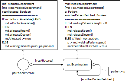
This process model defines the following two event rules.
| ON pa: PatientArrival |
|---|
| md : MedicalDepartment resAllocated : Boolean md := pa.medicalDepartment |
| IF md.isRoomAvailable() AND md.isDoctorAvailable() THEN md.allocateRoom(); md.allocateDoctor(); resAllocated := true ELSE md.waitingPatients.push( pa.patient); resAllocated := false |
| IF resAllocated SCHEDULE Examination( patient:=pa.patient, medicalDepartment:=md) |
| ON ex: Examination |
|---|
| md : MedicalDepartment anotherPatientFetched : Boolean p: Patient md := ex.medicalDepartment |
| IF md.waitingPatients.length = 0 THEN md.releaseRoom(); md.releaseDoctor(); anotherPatientFetched := false ELSE p := md.waitingPatients.pop(); anotherPatientFetched := true |
| IF anotherPatientFetched SCHEDULE Examination( patient:=p, medicalDepartment:=md) |
Notice that the event scheduling arrows of Figure 9-12, and also the SCHEDULE statements of the corresponding event rule tables, do not contain assignments of the duration of activities, since it is assumed that, by default, whenever an activity type has an operation duration(), the duration of activities of this type are assigned by invoking this operation.
A general model with resource objects as members of resource pools
In a more general approach, instead of using resource counter attributes, explicitly modeling resource object classes (like Room and Doctor) allows representing resource roles (stereotyped with «res») and resource pools (stereotyped with «pool») in the form of collections (like md.rooms and md.doctors) and modeling various forms of non-availability of resources (such as machines being defective or humans not being in the shift plan) with the help of corresponding resource status values (such as OUT_OF_ORDER). The result of this elaboration is the information design model shown in Figure 9-13.

For an OE class model, like the one shown in Figure 9-13, the following completeness constraint must hold: when an object type O (like Doctor) participates in a «res» association (a resource role association) with an activity type A (like Examination), the process owner object type of A (MedicalDepartment) must have a «pool» association with O.
Extending OE Class Diagrams by adding a «resource type» category
The
information design model of Figure 9-13 contains two
object types, Room and Doctor, which are the range of resource
role and resource pool properties (association ends stereotyped «res» and
«pool»). Such object types can be categorized as «resource type» with the
implied meaning that they inherit a resource status attribute from a
pre-defined class Resource, as shown in Figure 9-16.
Resource
The introduction of resource types to OEM class models allows simplifying models by dropping the following modeling items from OE class models, making them part of the implicit semantics:
- the status attributes of object types representing resource types, which are implicitly inherited;
- the pre-defined enumeration ResourceStatusEL;
- the resource management operations isAvailable, allocate and release, which are implicitly inherited by any resource type; and
- the planned activity queues may possibly be implicitly represented for any resource-constrained activity type in the form of ordered multi-valued reference properties of its process owner object type.

Revisiting the manufacturing workstation example
A manufacturing workstation, or a "server" in the terminology of Operation Research, represents a resource for the processing activities performed at/by it. This was left implicit in the OE class model shown on the right-hand side of Figure 8-3. Using the new modeling elements (resource types, resource roles and resource pools), the processing activities of a workstation can be explicitly modeled as resource-constrained activities, leading to the OE class model shown in Figure 9-17 and to a more high-level and more readable process model compared to the process model of Figure 8-4.

Decoupling the allocation of multiple resources
In a simplified simulation design for the extended scenario (with patients and nurses first walking to examination rooms before doctors are allocated for starting the examinations) described by the conceptual models of Figure 9-6 and Figure 9-9, we do not consider the walks of doctors, but only the walks of nurses and patients. For simplicity, we drop the superclass people and associate the activity type WalkToRoom with the Patient and Nurse classes. The result of this elaboration is the information design model shown in Figure 9-18.

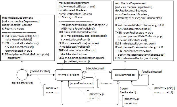
This process design model defines three event rules. Notice that the Examination event rule either re-allocates the doctor to the next planned examination and schedules it, if there is one, or it releases the doctor and re-allocates the room to the next planned walk-to-room and schedules it, if there is one.
Centralizing the re-allocation of resources
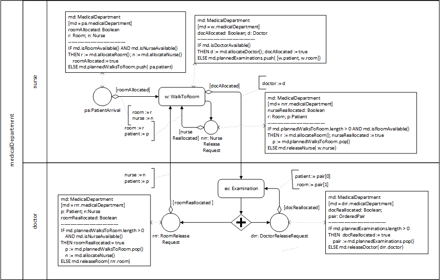
As shown before, in the conceptual process models of Figure 9-8 and Figure 9-9, the re-allocation of resources can be centralized with the help of resource release request events and the process owner and the involved performers can be displayed by using a Pool that is partitioned into Lanes for the involved activity performers, resulting in the model shown in Figure 9-20.
9.3. Introducing Resource-Dependent Activity Scheduling Arrows
The conceptual process model shown in Figure 9-9 and the process design model shown in Figure 9-20 exhibit a general pattern for modeling a sequence of two resource-constrained activities of types A1 and A2 shown in Figure 9-21. For describing this Allocate-Release Modeling Pattern, we assume that
- the process owner maintains queues for planned activities: q1 for for planned activities of type A1, and q2 for planned activities of type A2, both defined as queue-valued (i.e., ordered multi-valued) reference properties of the process owner in the underlying information model;
- the underlying information model specifies the sets of resources R1 and R2 required by A1 and A2;
- the set of resources required by A2 but not by A1 is denoted by R2−R1;
- the set of resources required by A1 and by A2 is denoted by R1∩R2.

We can describe the execution semantics of the Allocate-Release Modeling Pattern for the case of a succession of an activity of type A1 by another activity of type A2 in the following way:
- ON start event:
- If the resources R1 required by A1 are available, they are allocated; otherwise, a planned A1 activity is added to the task queue q1.
- If the resources R1 have been allocated, a new activity of type A1 is started.
- WHEN an activity of type A1 is
completed:
- If available, the resources R2−R1 are allocated; otherwise, a planned A2 activity with reserved resources R1∩R2 is added to the task queue q2.
- If R2−R1 have been allocated, a new activity of type A2 (with resources R2−R1 and R1∩R2) is started. In addition, the release of R1−R2 is requested.
- ON release request for
R1−R2:
- If q1 is not empty and the resources R1∩R2 required by both A1 and A2 are available, they are allocated and R1−R2 are re-allocated to head( q1); otherwise, R1−R2 are released.
- If the resources R1−R2 have been re-allocated, a new activity of type A1 is started.
- WHEN an activity of type A2 completes:
- There is no state change.
- An immediate release request for R2 is caused/scheduled.
- ON release request for R2:
- If R1∩R2 is nonempty: if q1 is not empty and the resources R1−R2 required by A1, but not yet allocated, are available, they are allocated and R1∩R2 are re-allocated to head( q1); otherwise, R1∩R2 are released. If q2 is not empty, then re-allocate R2−R1 to head( q2); otherwise, R2−R1 are released.
- If R1∩R2 have been re-allocated, a new activity of type A1 is started. If R2−R1 have been re-allocated, a new activity of type A2 is started.
Since the Allocate-Release Modeling Pattern defines a generic algorithm for scheduling resource-constrained activities as well as allocating and releasing resources, its (pseudo-)code does not have to be included in a DPMN Process Diagram, but can be delegated to an OE simulator supporting the resource-dependent scheduling of resource-constrained activities according to this pattern. This approach allows introducing new DPMN modeling elements for expressing the Allocate-Release Modeling Pattern in a concise way, either leaving allocate-release steps completely implicit, as in the DPMN Process Diagram of Figure 9-22, or explicitly expressing them, as in Figure 9-23.
The most important new DPMN modeling element introduced are Resource-Dependent Activity Scheduling (RDAS) arrows pointing to resource-constrained activities, as in Figure 9-22. These arrows are high-level modeling elements representing the implicit allocate-release logic exhibited in Figure 9-21. Thus, the meaning of the model of Figure 9-22 is provided by the model of Figure 9-21.

It is an option to display the implicit allocate-release steps with Allocate and Release rectangles together with simple control flow arrows, as between the start event circle and the Allocate R1 rectangle in Figure 9-23.

The meaning of the model of Figure 9-23 is the same as that of Figure 9-22, which is provided by the model of Figure 9-21. The fact that, using RDAS arrows, the allocate-release logic of resource-constrained activities does not have to be explicitly modeled and displayed in a process model shows the power of founding a process model on an information model, since the entire resource management logic can be expressed in terms of resource roles, constraints and pools in an information model. This is in contrast to the common approach of industrial simulation tools, such as Simio and AnyLogic, which require defining resource roles, constraints and pools as well as explicit allocate-release steps in the process model, in a similar way as shown in Figure 9-23.
The Standard Allocate-Release Algorithm
For each activity type, it has to be decided, if the resources required for a planned activity of that type are allocated at once or successively as soon as they become available. We call these two allocation policies Single-Step Allocation (SSA) and Multi-Step Allocation (MSA).
We can describe the Standard Allocate-Release Algorithm for the case of an event of type E succeeded by an activity of type A1 succeeded by another activity of type A2, with Ri and qi being the set of resource roles and the task queue of Ai, in the following way:
- WHEN an event e@t of type E occurs:
- A planned activity a of type A1 is created. If all R1 resources are available, they are allocated to a. Otherwise: (1) if MSA, then all available R1 resources are allocated to a; (2) a is added to the task queue q1.
- If all R1 resources have been allocated to a, it is started.
- WHEN an activity a1 of type
A1 is completed:
- A planned activity a2 of type A2 is created. If all R2−R1 resources are available, they are allocated to a2 and R1∩R2 are re-allocated from a1 to a2 (resulting in an allocation of all R2 resources to a2). Otherwise: (1) if MSA, then all available R2−R1 resources are allocated to a2 and R1∩R2 are re-allocated from a1 to a2; (2) a2 is added to q2.
- If all R2 resources have been allocated to a2, it is started. In addition, if MSA, the release of all R1−R2 resources is requested, else the release of all R1 resources is requested.
- ON release request for
R1−R2:
- If q1 is not empty and the resources R1∩R2 required by both A1 and A2 are available, they are allocated and R1−R2 are re-allocated to head( q1); otherwise, R1−R2 are released.
- If the resources R1−R2 have been re-allocated, a new activity of type A1 is started.
- WHEN an activity of type A2 completes:
- There is no state change.
- An immediate release request for R2 is caused/scheduled.
- ON release request for R2:
- If R1∩R2 is nonempty: if q1 is not empty and the resources R1−R2 required by A1, but not yet allocated, are available, they are allocated and R1∩R2 are re-allocated to head( q1); otherwise, R1∩R2 are released. If q2 is not empty, then re-allocate R2−R1 to head( q2); otherwise, R2−R1 are released.
- If R1∩R2 have been re-allocated, a new activity of type A1 is started. If R2−R1 have been re-allocated, a new activity of type A2 is started.
Since the Allocate-Release Modeling Pattern defines a generic algorithm for scheduling resource-constrained activities as well as allocating and releasing resources, its (pseudo-)code does not have to be included in a DPMN Process Diagram, but can be delegated to an OE simulator supporting the resource-dependent scheduling of resource-constrained activities according to this pattern. This approach allows introducing new DPMN modeling elements for expressing the Allocate-Release Modeling Pattern in a concise way, either leaving allocate-release steps completely implicit, as in the DPMN Process Diagram of Figure 9-22, or explicitly expressing them, as in Figure 9-23.
Connecting two Activity rectangles with an RDAS arrow in a DPMN process diagram implies DPMN's standard allocate-release algorithm according to which required resources that have not been allocated before are allocated immediately before an activity requiring them is started and released immediately after this activity is completed if they are not required by a successor activity. More precisely, when an activity of type A is completed, any resource that is not required by a successor activity of type B will be allocated to the next enqueued activity of type A, if there is one, or otherwise released.
Whenever another (non-standard) Allocate-Release logic is needed, it has to be expressed explicitly using conditional event scheduling arrows instead of RDAS arrows.
Example 1: Simplifying the workstation process model
We can now simplify the workstation model using the resource type category for WorkStation in the OE class model and a resource-dependent activity scheduling arrow from the arrival event to the processing activity in the DPMN process model. The resulting class model is shown in Figure 9-26.
The simplification of the process model of Figure 8-5 results in the model of Figure 9-25.

Example 2: Simplifying the medical department process model
We can now simplify the medical department model using the resource type category for Doctor, Room and Nurse in the OEM class model and resource-dependent activity scheduling arrows in the DPMN process model. The resulting class model is shown in Figure 9-26.
The simplification of the rather complex process model of Figure 9-20 by using resource-dependent activity scheduling arrows results in the model of Figure 9-27.
