Activity-Based Discrete Event Simulation
with OESjs-Core2
Copyright © 2020-2022 Gerd Wagner (CC BY-NC)
Published 2022-10-13
Abstract
This tutorial article explains how to use the OESjs-Core2 simulation library, which implements an architecture for Object Event Simulation (OES), extending the OESjs Core 1 simulator by adding support for activities, which are composite events with some duration. Activities are composed of a start event and an end event. Resource-constrained activities are modeled by means of Resource Roles (with Resource Cardinality Constraints) and Resource Pools. They can only be started when their required resources are available. Due to this dependency, a simulated activity cannot be scheduled like a simulated event. Rather, it has to be added to a queue of planned activities, from which it is dequeued, and scheduled via an immediate activity start event, as soon as the required resources become available.
Table of Contents
List of Figures
- 3-1. An OE class design model for the Load-Haul-Dump system.
- A-1. An information design model defining object, event and activity types.
- A-2. A process design for the Make-and-Deliver-Pizza business process
- A-3. An enriched process design model
- A-4. A conceptual OE class model describing object, event and activity types.
- A-5. A refined conceptual process model.
- A-6. An information design model for the Load-Haul-Dump system.
- A-7. A computationally complete process design for the Load-Haul-Dump business process.
- A-8. A design model for the
HaulRequestevent rule. - A-9. A design model for the
GoToLoadingSiteevent rule. - A-10. A design model for the
Loadevent rule. - A-11. A design model for the
Haulevent rule. - A-12. A design model for the
Dumpevent rule. - A-13. A design model for the
GoBackToLoadingSiteevent rule.
List of Tables
Chapter 1. Introduction to Object Event Modeling of Activities
This chapter shows how to make activity-based Discrete Event Simulation models using the paradigm of Object Event Modeling and Simulation (OEM&S) with UML Class Diagrams and DPMN Process Diagrams. It is recommended to first read the tutorial Discrete Event Simulation with OESjs-Core1.
Activities are composite events, having a start event and an end event, and a duration as the time in-between their start and end events.For modeling a discrete dynamic system with activities, we have to
- describe the object types, event types and activity types of the system (in an information model);
- describe for any resource-constrained activity type, its resource roles and associated resource pools (in the information model);
- specify, for any event type, the state changes of affected objects and the follow-up events caused by the occurrence of an event of that type (in a process model);
- specify, for any activity type, the state changes of affected objects and follow-up events caused by start and end events of activities of that type (in the process model).
Section 1.1. Making a Conceptual Model of the System under Investigation
As our first example, we consider a basic model of a medical department of a hospital with just one type of activity, medical examinations, and one type of resource, doctors. In our second example this model is extended by adding two other resource types, examination rooms and nurses, and another type of activity: walks to rooms (the walks of patients to examination rooms guided by nurses).
A basic conceptual model
In our basic model of a medical department we consider just one activity, medical examinations, and one type of resource, doctors:
- Patients arrive at a medical department at random times.
- If there are no other planned examinations waiting for the availability of a doctor, and a doctor is available, any newly arrived patient is immediately examined by that doctor. Otherwise, the planned examination of the newly arrived patient is added to a list of planned examinations (representing a queue).
- The duration of examinations varies, depending on the individual case.
- When an examination by a doctor is completed, the next planned examination is started by the doctor, if there is still any planned examination in the queue.
The potentially relevant object types of the system under investigation are:
- patients,
- medical departments,
- doctors.
The potentially relevant event types are:
- patient arrivals,
- examination starts,
- examination ends,
Instead of considering the event types examination starts and examination ends, we can consider the activity type examinations. Thus, we get the following conceptual information model (expressed as an OE Class Diagram, which is a special type of UML class diagram):

From the diagram we can infer that:
- For patient arrivals and for examinations, there is an association with medical departments providing the process owner, such that for any patient arrival event and examination activity a specific medical department is in charge of handling the event or seeing to it that the activity is going to be performed.
- While patient arrivals have two participants: a patient and a medical department, examinations have three participants: a patient, a medical department and a doctor.
- Examinations have one resource role, doctor, with a resource cardinality constraint of exactly one, which means that exactly one doctor is required for performing an examination.
- The process owner of an examination, a medical department, has a resource pool for doctors. The doctors needed for performing examinations at this department are allocated from this pool, and the department, as the process owner of examinations, has a business procedure for allocating doctors to planned examinations (using certain policies).
In addition to a conceptual information model, which captures the system's state structure, we also need to make a conceptual process model that captures the dynamics of the system. A process model can be expressed with the help of event rules, which define what happens when an event (of a certain type) occurs, or, more specifically, which state changes and which follow-up events are caused by an event of that type.
The following conceptual process model (in the form of a DPMN Process Diagram) is based on the information model above. It refers to a medical department as the process owner, visualized in the form of a container rectangle (called "Pool" in BPMN, but not in DPMN), and to doctor objects, as well as to the event type patient arrivals and to the activity type examinations.

This conceptual process model describes two causal regularities in the form of the following two event rules, each stated with two bullet points: one for describing the state changes and one for describing the follow-up events brought about by applying the rule.
When a new patient arrives:
- if a doctor is available, then she is allocated to the examination of that patient; otherwise, a new examination task (involving the newly arrived patient) is enqueued;
- if a doctor has been allocated, then the examination of the newly arrived patient is starts.
When an examination is completed by a doctor:
- if the queue of planned examinations is empty, then the doctor is released;
- otherwise, the next planned examination by that doctor starts immediately.
We can simplify the model by using a Resource-Dependent Activity Scheduling arrow between the patient arrivals event type circle and the examinations activity type rectangle, as shown in the following DPMN process diagram:

An extended conceptual model
For being more realistic, we consider the fact that patients first need to be walked by nurses to the room allocated to their examination before the examination can start. So, in our extended model of a medical department we consider two other resource types, examination rooms and nurses, and another type of activity: walks to rooms (the walks of patients to examination rooms guided by nurses):
- Patients arrive at a medical department at random times.
- When a new patient arrives, and an examination room and a nurse are available, that nurse walks the patient to that room, otherwise the patient has to wait for the availability of an examination room and a nurse (administratively, a new planned walk is added to the queue/list of planned walks).
- When a nurse has walked a patient to a room and a doctor is available, an examination of the patient by that doctor in the room starts; otherwise the patient has to wait for the availability of a doctor (administratively, a new planned examination is placed in the queue/list of planned examinations).
When an examination of a patient by a doctor in a room is completed,
- if there is still another planned examination of a patient waiting in a room for the availability of a doctor, the doctor goes to that room and starts the examination of that patient; otherwise, the planned examination of the newly arrived patient is added to a list of planned examinations (representing a queue);
- if there is still another planned walk of a patient to a room waiting for the availability of a room, the room is allocated to this planned walk; if a nurse is available, she walks the patient to that room.
- The duration of walks and examinations varies, depending on the individual case.
The potentially relevant object types of the system under investigation are: patients, medical departments, rooms, nurses and doctors.
The potentially relevant event types are patient arrivals and the activity types walks to rooms and examinations.
Thus, we get the following conceptual information model expressed as an OE class diagram:

Notice that in this model, (a) the performer role is explicitly marked with «performer»: a nurse is a performer of walks to room while a doctor is a performer of examinations, and (b) the stereotypes «resource role» and «resource pool» have been abbreviated by «rr» and «rp».
From the diagram we can infer that:
- For the event type patient arrivals and for the activity types walks to rooms and examinations, there is an association with medical departments providing the process owner.
- While patient arrivals have two participants: a patient and a medical department, walks and examinations have four participants: a medical department, a patient, a nurse or a doctor, and a room.
- Walks have two resource roles, nurse and room, both with a resource cardinality constraint of exactly one, which means that exactly one nurse and one room are required for performing a walk.
- Examinations have two resource roles, doctor and room, both with a resource cardinality constraint of exactly one.
- The process owner of a walk to a room and a subsequent examination, a medical department, has three resource pools for nurses, rooms and doctors. All required resources needed for performing walks to room and examinations at this department are allocated from these pools, and the department has corresponding business procedures for allocating rooms, nurses and doctors using certain allocation policies.
In addition to a conceptual information model, which captures the system's state structure, we also need to make a conceptual process model that captures the dynamics of the system. A process model can be expressed with the help of event rules, which define what happens when an event (of a certain type) occurs, or, more specifically, which state changes and which follow-up events are caused by an event of that type.
The following conceptual process model (in the form of a DPMN Process Diagram) is based on the information model above. It refers to the object types medical departments and doctors, as well as to the event type patient arrivals and to the activity type examinations.

This process model describes three causal regularities in the form of the following three event rules:
When a new patient arrives:
- if a room and a nurse are available, they are allocated to the walk of that patient to that room, otherwise a new planned walk is placed in the corresponding queue;
- if a room has been allocated, then the nurse starts walking the patient to the room.
When a walk of a patient and nurse to a room is completed:
- if there is still a planned walk in the queue and a room is available, then the room is allocated and the nurse is re-allocated to the walk of the next patient to that room;
if a doctor is available, she is allocated to the examination of that patient, else a new planned examination of that patient is queued up; - if a doctor has been allocated, then the examination of the patient starts;
if the nurse has been re-allocated, she starts walking the next patient to the allocated room.
- if there is still a planned walk in the queue and a room is available, then the room is allocated and the nurse is re-allocated to the walk of the next patient to that room;
When an examination of a patient is completed by a doctor in a particular room:
- if there is still a planned examination (of another patient in another room), the doctor is re-allocated to that planned examination, else the doctor is released;
if the waiting line is not empty, the room is re-allocated to the next patient, else it is released; - if the doctor has been re-allocated to a planned examination, that examination starts;
if the room has been re-allocated to another patient and a nurse is available, that nurse starts walking the patient to the room.
- if there is still a planned examination (of another patient in another room), the doctor is re-allocated to that planned examination, else the doctor is released;
Again, we can simplify the model by using Resource-Dependent Activity Scheduling arrows resulting in an Activity Network model, as shown in the following DPMN process diagram:

We can display the two performer roles doctor and nurse with the help of two corresponding swimlanes shown within the process rectangle:

Notice that the use of swimlanes (marking disjoint subrectangles) is a convenient visual syntax for displaying the performer roles when the different performers have a non-overlapping set of activity types. However, when activities of a certain type are performed jointly by more than one performer (e.g., when a doctor and a nurse jointly perform an examination), a different visual syntax needs to be introduced.
Section 1.2. Making Simulation Design Models
When making a simulation design based on a conceptual model of the system under investigation, we may abstract away from certain items of the conceptual model for obtaining a sufficiently simple design. The right degree of abstraction depends on the purpose of the model.
In our example of a medical department, the purpose of the simulation model is to compute the maximum queue length and the resource utilization for all types of activities. So, we may abstract away from the object type patients since we don't need any information about individual patients. If we don't need utilization statistics per doctor, but only the average utilization of all doctors, then we may also abstract away from the object type doctors This is the approach chosen in our design models Medical-Department-1a and Medical-Department-1b, while we keep the object type doctors for modeling individual doctors in the design model Medical-Department-1c.
Since we abstract away from individual patients, we rename patient arrival events to NewCase events, each of them representing a new case for an examination to be planned and performed.
The event type NewCase is a type of exogenous events, which are not caused by any causal regularity of the system under investigation and, therefore, have to be modeled with a recurrence function that allows to compute the time of the next occurrence of an event of that type.
1.2.1. Design models based on the basic conceptual model
We model the random variations of two variables, the recurrence of new cases and the duration of examinations, in the form of random variables as special class-level ("static") functions, with a stereotype «rv», in the class to which they belong, as shown in the diagrams below.
The recurrence of NewCase events is modeled as a random variable with an exponential distribution having an event rate of 0.7 per minute. The duration of examinations is modeled as a random variable with a uniform distribution having lower bound 5 and upper bound 9.
The Medical-Department-1a design model
In the Medical-Department-1a information design model, instead of using the built-in generic resource management logic, we explicitly model the resource management of doctors with the help of a counter variable for available doctors in the form of an attribute nmrOfAvailableDoctors, and the operations isDoctorAvailable(), allocateDoctor() and releaseDoctor(), in the MedicalDepartment class:

The isDoctorAvailable function simply tests if nmrOfAvailableDoctors > 0, while the procedures allocateDoctor and releaseDoctor decrement and increment the nmrOfAvailableDoctors counter.
In addition to an information design model for defining the simulation's state structure, we also need to make a process design model for defining the dynamics of the simulation. The following DPMN process diagram defines two event rules:

Notice that this process design model contains the entire resource management logic for (de-)allocating doctors to (from) examinations. Since standard resource management procedures can be defined in a generic way, this logic (and the related code) can be moved from example models to the simulator, as explained in the next section.
The following table shows the two event rules defined by the above DPMN diagram, expressed in pseudo-code.
ON (event type) | DO (event routine) |
NewCase( md) @ t | newExam = new Examination( md); IF md.isDoctorAvailable() md.allocateDoctor(); SCHEDULE new ActivityStart( newExam); ELSE md.plannedExaminations.enqueue( newExam); |
Examination( md) @ t | IF md.plannedExaminations.length = 0 md.releaseDoctor(); ELSE plannedExam = md.plannedExaminations.dequeue(); SCHEDULE new ActivityStart( plannedExam); |
The Medical-Department-1b design model
In the Medical-Department-1b information design model we make two simplifications:
- We drop the object type MedicalDepartment; since we only need to model one medical department as the process owner, we can leave it implicit. This is a general pattern: whenever there is only one process owner, we can leave it implicit.
- Since we now use the generic resource management logic that is built into OES Core 2, we do not need to model the methods isDoctorAvailable, allocateDoctor and releaseDoctor. Instead, we define a resource role doctor (with resource cardinality 1) for the activity type Examination.
The resulting information design model only includes two classes: the event type NewCase and the activity type Examination, as shown on the left-hand side of the following class diagram.

On the right-hand side bottom of this diagram, the resource role doctor and its count pool doctors, instantiating the OES Core 2 library classes ResourceRole and CountPool (as a special type of ResourcePool), are shown. Notice that resourceRole assigns the OES resource role doctor with resource cardinality 1 to the activity type Examination[1], which is in turn linked to a count pool with name doctors. In OESjs-Core2, this is coded in the file Examination.js in the following way:
class Examination extends aCTIVITY {
  constructor({id, startTime, duration}={}) {
    super({id, startTime, duration});
  }
  static duration() {return rand.uniform( 5, 10);}
}
Examination.resourceRoles = {
  "doctor": {card:1}
}
The generic class-level ("static") property Examination.tasks is automatically created by the simulator. Likewise, the count pool "doctors" is automatically created and assigned to the resource role definition map entry Examination.resourceRoles["doctor"].
In the Medical-Department-1b process design model we make corresponding simplifications as in the information design model above:
- Leaving the process owner implicit, we drop the process owner rectangle MedicalDepartment.
- Since we use the generic resource management logic that is built into OES Core 2 by means of Resource-Dependent Activity Start arrows, we do not need any resource management code involving the methods isDoctorAvailable, allocateDoctor and releaseDoctor in event rules. Since the event rules of the Medical-Department-1a model have only be concerned with resource management, we can discard them altogether.
In the resulting DPMN diagram, the event type NewCase is connected to the activity type Examination with a Resource-Dependent Activity Scheduling arrow:

Using a Resource-Dependent Activity Scheduling arrow from NewCase to Examination implies that upon a NewCase event a new planned Examination activity is enqueued by the simulator, if the required resources are not available; otherwise, a new Examination activity is scheduled to start immediately. Using this built-in standard resource management logic relieves the simulation developer from coding the resource availability tests and the enqueuing of a new Examination activity in a NewCase event rule.
Since in this model, NewCase events and Examination activities are handled according to the generic logic of Activity Networks built into the OES Core 2 simulator, we do not need to model/specify any event rules. For having NewCase events succeeded by Examination activities, we just need to specify this event flow relationship (in OESjs-Core2) in the following way:
NewCase.successorActivity = "Examination";
The simulator interprets this successorActivity assignment when creating follow-up events for NewCase events by enqueuing a planned examination activity in the following way
Examination.tasks.enqueue( new Examination())
The Medical-Department-1c design model
In the Medical-Department-1c design model, the resource pool doctors is modeled as an individual resource pool instead of a count pool. This allows making the model more realistic, for instance, by assigning an individual work schedule to each doctor defining her availability.
Compared to the Medical-Department-1b information design model, we have to change the following:
- We need to define an object type Doctor having a resource status attribute with the four possible values AVAILABLE, BUSY, OUT_OF_ORDER or OUT_OF_DUTY.
- While we keep the resourceRole link with the definition of the resource role doctor (with resource cardinality 1), we replace the count pool linked to it with an individual resource pool.
The resulting information design model is shown in the following class diagram:

On the right-hand side bottom of this diagram, the resource role doctor and its individual pool doctors, instantiating the OES Core 2 library classes ResourceRole and IndividualPool (as a special type of ResourcePool), are shown. In OESjs-Core2, this is coded in the file Examination.js in the following way:
Examination.resourceRoles = {
  "doctor": {range: Doctor, card:1}
}
The Medical-Department-1c process design model is the same as in the Medical-Department-1b process design model above:
1.2.2. A design model based on the extended conceptual model
In the Medical-Department-2a design model, we model two activity types: WalkToRoom activities involve a room and are performed by a nurse, while Examination activities involve a room and are performed by a doctor. The resource pools nurses and doctors are modeled as individual resource pools, while the resource pool rooms, which is used by both WalkToRoom and Examination activities, is modeled as a count pool.
The resulting information design model is shown in the following class diagram:

Notice that the generic class-level ("static") properties WalkToRoom.tasks and Examination.tasks don't have to be defined when coding the two activity types since they are automatically created by the simulator.
In the process design model, again, we leave the process owner implicit, not showing a container rectangle for MedicalDepartment:
However, it is an option to show the performer roles with the help of corresponding Lanes:

In OESjs-Core2, the two Resource-Dependent Activity Scheduling arrows between NewCase and WalkToRoom, as well as between WalkToRoom and Examination are coded as
NewCase.successorActivity = "WalkToRoom";
in the file NewCase.js, and as
WalkToRoom.successorActivity = "Examination";
in WalkToRoom.js.
Chapter 2. Activity-Based Discrete Event Simulation with OESjs-Core2
The JavaScript-based simulation framework OESjs-Core2 implements the Object Event Simulation (OES) paradigm, allowing activity-based Discrete Event Simulation based on object-oriented modeling and event scheduling. You can download OESjs-Core2 in the form of a ZIP archive file from the OES GitHub repo. After extracting the archive on your local disk, you can run any of its example models or create your own model (e.g., by making a copy of one of the example model folders and using its code files a s starting point).
The code of an OESjs-Core2 simulation consists of (1) the OESjs-Core2 library files in the folder OESjs-Core2, (2) general library files in the lib folder and (3) the following files to be created by the simulation developer:
- For each object type ObjT, a JS code file ObjT.js.
- For each event type EvtT, a JS code file EvtT.js.
- For each activity type ActT, a JS code file ActT.js.
- A simulation.js file defining further parts of the simulation, such as statistics variables and the initial state.
OESjs-Core2 supports three forms of simulations:
Standalone scenario simulations, which are good for getting a quick impression of a simulation model, e.g., by checking some simple statistics.
Simple simulation experiments, which are defined as a set of replicated simulation scenario runs, providing summary statistics like mean, standard deviation, minimum/maximum and confidence intervals for each statistics variable defined in the underlying model.
Parameter variation experiments, for which a set of experiment parameters with value sets are defined such that each experiment parameter corresponds to a model parameter. When an experiment is run, each experiment parameter value combination defines an experiment scenario, which is run repeatedly, according to the specified number or replications for collecting statistics.
OESjs-Core2 allows defining two or more simulation scenarios for a given model. While an experiment type is defined for a given model, an experiment of that type is run on top of a specific scenario.
Using a simulation library like OESjs-Core2 means that only the model-specific logic has to be coded (in the form of object types, event types, event routines and other functions for model-specific computations), but not the general simulator operations (e.g., time progression and statistics) and the environment handling (e.g., user interfaces for statistics output).
The following sections present the basic concepts of the OESjs-Core2 simulation library, and show how to implement the models described in Chapter 1.
You can download the simulation example folders from the OES repo to your computer, and then possibly modify their files for creating your own simulations. Since an OESjs simulation includes a JS worker file for running the simulator in its own thread separately from the main (user interface) thread, it cannot be run from the local file system without changing the browser's default configuration (due to the web security policy CORS).
For developing OESjs simulations on your computer, you should use Firefox because its security settings can be easily configured such that it allows loading JS worker files directly from the local file system by disabling the flag "strict_origin_policy" specifically for file URLs:
Enter "about:config" in the Firefox search bar.
Search for "security.fileuri.strict_origin_policy".
Disable this policy by changing its value from true to false.
This creates only a small security risk because the important web security policy called "CORS" is only disabled for file URLs, but not for normal URLs.
For other browsers, like Chrome, you need to install a local HTTP server and load your simulation's index.html file from that local server, or run it via the JS development tool WebStorm (which has a built-in local server), because the only option for loading JS worker files from the local file system in Chrome would be to disable the CORS policy completely (see how to disable CORS in Chrome), but that would create a severe security risk and is therefore not recommended.
Section 2.1. Simulation Time
A simulation model has an underlying time model, which can be either discrete time, when setting
sim.model.time = "discrete";
or continuous time, when setting
sim.model.time = "continuous";
Choosing a discrete time model means that time is measured in steps (with equal durations), and all temporal random variables used in the model need to be discrete (i.e., based on discrete probability distributions). Choosing a continuous time model means that one has to define a simulation time granularity, as explained in the next sub-section.
In both cases, the underlying simulation time unit can be either left unspecified (e.g., in the case of an abstract time model), or it can be set to one of the time units "ms", "s", "min", "hour", "day", "week", "month" or "year", as in
sim.model.timeUnit = "hour";
Typical examples of time models are:
An abstract discrete model of time where time runs in steps without any concrete meaning:
sim.model.time = "discrete";
A concrete discrete model of time in number of days:
sim.model.time = "discrete";
sim.model.timeUnit = "day";
A concrete continuous model of time in number of seconds:
sim.model.time = "continuous";
sim.model.timeUnit = "s";
2.1.1. Time Granularity
A model's time granularity is the time delay until the next moment, such that the model does not allow considering an earlier next moment. This is captured by the simulation parameter nextMomentDeltaT used by the simulator for scheduling immediate events with a minimal delay. When a simulation model is based on discrete time, nextMomentDeltaT is set to 1, referring to the next time point. When a simulation model is based on continuous time, nextMomentDeltaT is set to the default value 0.001, unless the model parameter sim.model.nextMomentDeltaT is explicitly assigned in the simulation.js file.
2.1.2. Time Progression
An important issue in simulation is the question how the simulation time is advanced by the simulator. The OES paradigm supports next-event time progression and fixed-increment time progression, as well as their combination.
An OESjs-Core1 model with fixed-increment time progression has to define a suitable periodic time event type, like EachSecond or EachDay in the form of an exogenous event type with a recurrence function returning the value 1. Such a model can be used for
- modeling continuous state changes (e.g., objects moving in a continuous space), or
- making a discrete model that abstracts away from explicit events and uses only implicit periodic time events ("ticks"), which is a popular approach in social science simulation.
Examples of discrete event simulation models with fixed-increment time progression and no explicit events are the Schelling Segregation Model and the Susceptible-Infected-Recovered (SIR) Disease Model.
Section 2.2. Simulation Models
2.2.1. An Activity Type with a Class-Level Resource Role and a Count Pool
Based on the conceptual model of Section 1.1, we choose the design discussed in Section 1.2 in the subsection "The Medical-Department-1b design model" and defined by the following information design model:
Notice that this model
Does not define an object type Doctor, since the doctors of the department are not modeled as a collection of individual persons, but as an abstract aggregate in the form of a count pool.
- Does not link the resource role doctor to the count pool doctors because linking a resource pool to an activity type for any of its resource roles has to be done by a process model, either implicitly or explicitly. By default, if there is a resource pool with the same (but pluralized) name as a resource role, it is implicitly assigned to that resource role. In general, an information design model may be the basis for many process models, and each of them may assign a different resource pool to the same resource role of an activity type.
The random variable recurrence for modeling the random variation of the time between new cases samples from the exponential probability distribution with an event rate of 0.3, while the random variable for the duration of an examination samples from the uniform probability distribution with lower bound 5 and upper bound 10 (representing minutes).
The NewCase class can be coded with OESjs-Core2 in the following way:
class NewCase extends eVENT {
  constructor({ occTime, delay}) {
    super({occTime, delay});
  }
  onEvent() {return [];}
  createNextEvent() {
    return new NewCase({delay: NewCase.recurrence()});
  }
  static recurrence() {return rand.exponential( 0.3);}
}
The onEvent method is empty since no event rules are needed for this simple model. Its dynamics is entirely determined by the standard logic of resource-dependent activity scheduling built into OES Core 2.
The Examination class can be coded in the following way:
class Examination extends aCTIVITY {
  constructor({id, startTime, duration}={}) {
    super({id, startTime, duration});
  }
  static duration() {return rand.uniform( 5, 10);}
}
Examination.resourceRoles = {
    "doctor": {countPoolName:"doctors", card:1}
}
The process resulting from NewCase events followed by Examination activities is modeled with a Resource-Dependent Activity Scheduling arrow:
In OESjs-Core2, this simple process model is coded with one line of code in the file NewCase.js:
NewCase.successorActivity = "Examination";
2.2.2. Modeling a Sequence of Two Activity Types
The following information design model of a medical department with two types of activities (discussed in ) is based on the conceptual information model discussed in :
The class implementing the event type NewCase is defined as above. The class implementing the activity type WalkToRoom is defined as follows:
class WalkToRoom extends aCTIVITY {
  constructor({id, startTime, duration}={}) {
    super({id, startTime, duration});
  }
  static duration() {return rand.uniform( 0.5, 2.5);}
}
// A walk to a room requires a room and a nurse
WalkToRoom.resourceRoles = {
  "nurse": {range: Nurse, card:1},
  "room": {countPoolName:"rooms", card:1}
}
The class implementing the activity type Examination is defined as follows:
class Examination extends aCTIVITY {
  constructor({id, startTime, duration}={}) {
    super({id, startTime, duration});
  }
  static duration() {return rand.uniform( 5, 10);}
}
// An examination requires a room and a doctor
Examination.resourceRoles = {
  "doctor": {range: Doctor, card:1},
  "room": {countPoolName:"rooms", card:1}
}
The following process design model (discussed in ) is based on the conceptual process model discussed in :
This process design model with its two Resource-Dependent Activity Scheduling arrows is implemented with just two statements on top of the classes NewCase and WalkToRoom:
// Enqueue a new planned walk
NewCase.successorActivity = "WalkToRoom";
// Enqueue a new planned examination
WalkToRoom.successorActivity = "Examination";
You can run this Medical-Department-2a model from the project's GitHub website.
Activities with Default Durations
When an activity type is defined without defining a class-level duration function, the exponential PDF is used as a built-in default random variable for setting the durations of activities of that type according to the following settings:
aCTIVITY.defaultMean = 1;
aCTIVITY.defaultDuration = function () {
  return rand.exponential( 1/aCTIVITY.defaultMean)
};
It is possible to overwrite these defaults, both the defaultMean and the defaultDuration function, in a simulation.js file.
Section 2.3. Simulation Scenarios
For obtaining a complete executable simulation scenario, a simulation model has to be complemented with simulation parameter settings and an initial system state.
In general, we may have more than one simulation scenario for a simulation model. For instance, the same model could be used in two different scenarios with different initial states.
2.3.1. A Simulation Scenario for Medical-Department-1b
The default simulation scenario for the Medical-Department-1b model defines a duration of 1000 min per simulation run and an initial state with a count resource pool with 3 doctors:
sim.scenario.durationInSimTime = 1000;
sim.scenario.setupInitialState = function () {
  // Initialize the count pool "doctors"
  sim.resourcePools["doctors"].available = 3;
  // Schedule initial events
  sim.FEL.add( new NewCase({occTime: 1}));
}
You can run this Medical-Department-1b scenario from the project's GitHub website. An example of a run of this scenario is shown in the following simulation log:
| Step | Time | System State | Future Events |
|---|---|---|---|
| 1 | 1 | av. doctors: 2 | ExaminationStart@1.01, NewCase@3.33 |
| 2 | 1.01 | av. doctors: 2 | NewCase@3.33, ExaminationEnd@8.72 |
| 3 | 3.33 | av. doctors: 1 | ExaminationStart@3.34, NewCase@4.59, ExaminationEnd@8.72 |
| 4 | 3.34 | av. doctors: 1 | NewCase@4.59, ExaminationEnd@8.72, ExaminationEnd@12.51 |
| 5 | 4.59 | av. doctors: 0 | ExaminationStart@4.6, NewCase@6.93, ExaminationEnd@8.72, ExaminationEnd@12.51 |
| 6 | 4.6 | av. doctors: 0 | NewCase@6.93, ExaminationEnd@8.72, ExaminationEnd@12.51, ExaminationEnd@13.71 |
| 7 | 6.93 | av. doctors: 0 | ExaminationEnd@8.72, NewCase@8.79, ExaminationEnd@12.51, ExaminationEnd@13.71 |
| 8 | 8.72 | av. doctors: 0 | ExaminationStart@8.73, NewCase@8.79, ExaminationEnd@12.51, ExaminationEnd@13.71 |
| 9 | 8.73 | av. doctors: 0 | NewCase@8.79, ExaminationEnd@12.51, ExaminationEnd@13.71, ExaminationEnd@16.58 |
| 10 | 8.79 | av. doctors: 0 | NewCase@9.56, ExaminationEnd@12.51, ExaminationEnd@13.71, ExaminationEnd@16.58 |
| 11 | 9.56 | av. doctors: 0 | ExaminationEnd@12.51, ExaminationEnd@13.71, ExaminationEnd@16.58, NewCase@17.88 |
| 12 | 12.51 | av. doctors: 0 | ExaminationStart@12.52, ExaminationEnd@13.71, ExaminationEnd@16.58, NewCase@17.88 |
| 13 | 12.52 | av. doctors: 0 | ExaminationEnd@13.71, ExaminationEnd@16.58, NewCase@17.88, ExaminationEnd@19.95 |
| 14 | 13.71 | av. doctors: 0 | ExaminationStart@13.72, ExaminationEnd@16.58, NewCase@17.88, ExaminationEnd@19.95 |
| 15 | 13.72 | av. doctors: 0 | ExaminationEnd@16.58, NewCase@17.88, ExaminationEnd@19.95, ExaminationEnd@22.08 |
| 16 | 16.58 | av. doctors: 1 | NewCase@17.88, ExaminationEnd@19.95, ExaminationEnd@22.08 |
| 17 | 17.88 | av. doctors: 0 | ExaminationStart@17.89, NewCase@18.06, ExaminationEnd@19.95, ExaminationEnd@22.08 |
| 18 | 17.89 | av. doctors: 0 | NewCase@18.06, ExaminationEnd@19.95, ExaminationEnd@22.08, ExaminationEnd@23.95 |
| 19 | 18.06 | av. doctors: 0 | ExaminationEnd@19.95, ExaminationEnd@22.08, ExaminationEnd@23.95, NewCase@24.76 |
| 20 | 19.95 | av. doctors: 0 | ExaminationStart@19.96, ExaminationEnd@22.08, ExaminationEnd@23.95, NewCase@24.76 |
| 21 | 19.96 | av. doctors: 0 | ExaminationEnd@22.08, ExaminationEnd@23.95, NewCase@24.76, ExaminationEnd@27.37 |
| 22 | 22.08 | av. doctors: 1 | ExaminationEnd@23.95, NewCase@24.76, ExaminationEnd@27.37 |
| 23 | 23.95 | av. doctors: 2 | NewCase@24.76, ExaminationEnd@27.37 |
| 24 | 24.76 | av. doctors: 1 | ExaminationStart@24.77, ExaminationEnd@27.37, NewCase@27.97 |
| 25 | 24.77 | av. doctors: 1 | ExaminationEnd@27.37, NewCase@27.97, ExaminationEnd@32.74 |
| 26 | 27.37 | av. doctors: 2 | NewCase@27.97, ExaminationEnd@32.74 |
| 27 | 27.97 | av. doctors: 1 | ExaminationStart@27.98, NewCase@32.5, ExaminationEnd@32.74 |
| 28 | 27.98 | av. doctors: 1 | NewCase@32.5, ExaminationEnd@32.74, ExaminationEnd@36.51 |
| 29 | 32.5 | av. doctors: 0 | ExaminationStart@32.51, NewCase@32.73, ExaminationEnd@32.74, ExaminationEnd@36.51 |
| 30 | 32.51 | av. doctors: 0 | NewCase@32.73, ExaminationEnd@32.74, ExaminationEnd@36.51, ExaminationEnd@37.93 |
| 31 | 32.73 | av. doctors: 0 | ExaminationEnd@32.74, NewCase@34.02, ExaminationEnd@36.51, ExaminationEnd@37.93 |
| 32 | 32.74 | av. doctors: 0 | ExaminationStart@32.75, NewCase@34.02, ExaminationEnd@36.51, ExaminationEnd@37.93 |
| 33 | 32.75 | av. doctors: 0 | NewCase@34.02, ExaminationEnd@36.51, ExaminationEnd@37.93, ExaminationEnd@39.84 |
| 34 | 34.02 | av. doctors: 0 | ExaminationEnd@36.51, ExaminationEnd@37.93, ExaminationEnd@39.84, NewCase@40.99 |
| 35 | 36.51 | av. doctors: 0 | ExaminationStart@36.52, ExaminationEnd@37.93, ExaminationEnd@39.84, NewCase@40.99 |
| 36 | 36.52 | av. doctors: 0 | ExaminationEnd@37.93, ExaminationEnd@39.84, NewCase@40.99, ExaminationEnd@44.03 |
| 37 | 37.93 | av. doctors: 1 | ExaminationEnd@39.84, NewCase@40.99, ExaminationEnd@44.03 |
| 38 | 39.84 | av. doctors: 2 | NewCase@40.99, ExaminationEnd@44.03 |
| 39 | 40.99 | av. doctors: 1 | ExaminationStart@41, ExaminationEnd@44.03, NewCase@59.51 |
| 40 | 41 | av. doctors: 1 | ExaminationEnd@44.03, ExaminationEnd@47.52, NewCase@59.51 |
| 41 | 44.03 | av. doctors: 2 | ExaminationEnd@47.52, NewCase@59.51 |
| 42 | 47.52 | av. doctors: 3 | NewCase@59.51 |
| 43 | 59.51 | av. doctors: 2 | ExaminationStart@59.52, NewCase@66.71 |
| 44 | 59.52 | av. doctors: 2 | ExaminationEnd@64.6, NewCase@66.71 |
| 45 | 64.6 | av. doctors: 3 | NewCase@66.71 |
| 46 | 66.71 | av. doctors: 2 | ExaminationStart@66.72, NewCase@78.2 |
| 47 | 66.72 | av. doctors: 2 | ExaminationEnd@74.77, NewCase@78.2 |
| 48 | 74.77 | av. doctors: 3 | NewCase@78.2 |
| 49 | 78.2 | av. doctors: 2 | ExaminationStart@78.21, NewCase@80.27 |
| 50 | 78.21 | av. doctors: 2 | NewCase@80.27, ExaminationEnd@83.75 |
| 51 | 80.27 | av. doctors: 1 | ExaminationStart@80.28, NewCase@80.53, ExaminationEnd@83.75 |
| 52 | 80.28 | av. doctors: 1 | NewCase@80.53, ExaminationEnd@83.75, ExaminationEnd@89.82 |
| 53 | 80.53 | av. doctors: 0 | ExaminationStart@80.54, NewCase@80.77, ExaminationEnd@83.75, ExaminationEnd@89.82 |
| 54 | 80.54 | av. doctors: 0 | NewCase@80.77, ExaminationEnd@83.75, ExaminationEnd@89.62, ExaminationEnd@89.82 |
| 55 | 80.77 | av. doctors: 0 | NewCase@81.44, ExaminationEnd@83.75, ExaminationEnd@89.62, ExaminationEnd@89.82 |
In the Medical-Department-1c model, which is a variant of Medical-Department-1b, the count pool for doctors is replaced with an individual pool.
2.3.1. A Simulation Scenario for Medical-Department-2
The default simulation scenario for the Medical-Department-2 model defines an initial state with three doctors in the individual pool "doctors", two nurses in the individual pool "nurses" and three rooms in the count pool "rooms":
sim.scenario.durationInSimTime = 1000;
sim.scenario.setupInitialState = function () {
  const d1 = new Doctor({id: 1, status: oes.ResourceStatusEL.AVAILABLE}),
      d2 = new Doctor({id: 2, status: oes.ResourceStatusEL.AVAILABLE}),
      d3 = new Doctor({id: 3, status: oes.ResourceStatusEL.AVAILABLE}),
      n1 = new Nurse({id: 11, status: oes.ResourceStatusEL.AVAILABLE}),
      n2 = new Nurse({id: 12, status: oes.ResourceStatusEL.AVAILABLE});
  // Initialize the individual resource pools
  sim.resourcePools["doctors"].availResources.push( d1, d2, d3);
  sim.resourcePools["nurses"].availResources.push( n1, n2);
  // Initialize the count pools
  sim.resourcePools["rooms"].available = 3;
  // Schedule initial events
  sim.FEL.add( new NewCase({occTime: 1}));
}
You can run this Medical-Department-2a scenario from the project's GitHub website. An example of a run of this scenario is shown in the following simulation log:
| Step | Time | System State | Future Events |
|---|---|---|---|
| 1 | 1 | Doctor-1{ st: 1}, Doctor-2{ st: 1}, Doctor-3{ st: 1}, Nurse-11{ st: 2}, Nurse-12{ st: 1} | av. nurses: n2, av. rooms: 2, av. doctors: d1,d2,d3 | WalkToRoomStart{n1}@1.01, NewCase@1.85 |
| 2 | 1.01 | Doctor-1{ st: 1}, Doctor-2{ st: 1}, Doctor-3{ st: 1}, Nurse-11{ st: 2, act: {WalkToRoom}}, Nurse-12{ st: 1} | av. nurses: n2, av. rooms: 2, av. doctors: d1,d2,d3 | NewCase@1.85, WalkToRoomEnd{n1}@2.28 |
| 3 | 1.85 | Doctor-1{ st: 1}, Doctor-2{ st: 1}, Doctor-3{ st: 1}, Nurse-11{ st: 2, act: {WalkToRoom}}, Nurse-12{ st: 2} | av. nurses: , av. rooms: 1, av. doctors: d1,d2,d3 | WalkToRoomStart{n2}@1.86, WalkToRoomEnd{n1}@2.28, NewCase@6.27 |
| 4 | 1.86 | Doctor-1{ st: 1}, Doctor-2{ st: 1}, Doctor-3{ st: 1}, Nurse-11{ st: 2, act: {WalkToRoom}}, Nurse-12{ st: 2, act: {WalkToRoom}} | av. nurses: , av. rooms: 1, av. doctors: d1,d2,d3 | WalkToRoomEnd{n1}@2.28, WalkToRoomEnd{n2}@3.99, NewCase@6.27 |
| 5 | 2.28 | Doctor-1{ st: 2}, Doctor-2{ st: 1}, Doctor-3{ st: 1}, Nurse-11{ st: 1, act: {}}, Nurse-12{ st: 2, act: {WalkToRoom}} | av. nurses: n1, av. rooms: 1, av. doctors: d2,d3 | ExaminationStart{ d1}@2.29, WalkToRoomEnd{n2}@3.99, NewCase@6.27 |
| 6 | 2.29 | Doctor-1{ st: 2, act: {Examination}}, Doctor-2{ st: 1}, Doctor-3{ st: 1}, Nurse-11{ st: 1, act: {}}, Nurse-12{ st: 2, act: {WalkToRoom}} | av. nurses: n1, av. rooms: 1, av. doctors: d2,d3 | WalkToRoomEnd{n2}@3.99, NewCase@6.27, ExaminationEnd{ d1, }@10.83 |
| 7 | 3.99 | Doctor-1{ st: 2, act: {Examination}}, Doctor-2{ st: 2}, Doctor-3{ st: 1}, Nurse-11{ st: 1, act: {}}, Nurse-12{ st: 1, act: {}} | av. nurses: n1,n2, av. rooms: 1, av. doctors: d3 | ExaminationStart{ d2}@4, NewCase@6.27, ExaminationEnd{ d1, }@10.83 |
| 8 | 4 | Doctor-1{ st: 2, act: {Examination}}, Doctor-2{ st: 2, act: {Examination}}, Doctor-3{ st: 1}, Nurse-11{ st: 1, act: {}}, Nurse-12{ st: 1, act: {}} | av. nurses: n1,n2, av. rooms: 1, av. doctors: d3 | NewCase@6.27, ExaminationEnd{ d1}@10.83, ExaminationEnd{ d2, }@13.28 |
| 9 | 6.27 | Doctor-1{ st: 2, act: {Examination}}, Doctor-2{ st: 2, act: {Examination}}, Doctor-3{ st: 1}, Nurse-11{ st: 2, act: {}}, Nurse-12{ st: 1, act: {}} | av. nurses: n2, av. rooms: 0, av. doctors: d3 | WalkToRoomStart{n1}@6.28, NewCase@7.19, ExaminationEnd{ d1, }@10.83, ExaminationEnd{ d2}@13.28 |
| 10 | 6.28 | Doctor-1{ st: 2, act: {Examination}}, Doctor-2{ st: 2, act: {Examination}}, Doctor-3{ st: 1}, Nurse-11{ st: 2, act: {WalkToRoom}}, Nurse-12{ st: 1, act: {}} | av. nurses: n2, av. rooms: 0, av. doctors: d3 | NewCase@7.19, WalkToRoomEnd{n1}@8.77, ExaminationEnd{ d1, }@10.83, ExaminationEnd{ d2}@13.28 |
| 11 | 7.19 | Doctor-1{ st: 2, act: {Examination}}, Doctor-2{ st: 2, act: {Examination}}, Doctor-3{ st: 1}, Nurse-11{ st: 2, act: {WalkToRoom}}, Nurse-12{ st: 1, act: {}} | av. nurses: n2, av. rooms: 0, av. doctors: d3 | NewCase@8.5, WalkToRoomEnd{n1}@8.77, ExaminationEnd{ d1, }@10.83, ExaminationEnd{ d2}@13.28 |
| 12 | 8.5 | Doctor-1{ st: 2, act: {Examination}}, Doctor-2{ st: 2, act: {Examination}}, Doctor-3{ st: 1}, Nurse-11{ st: 2, act: {WalkToRoom}}, Nurse-12{ st: 1, act: {}} | av. nurses: n2, av. rooms: 0, av. doctors: d3 | WalkToRoomEnd{n1}@8.77, ExaminationEnd{ d1}@10.83, NewCase@13.06, ExaminationEnd{ d2}@13.28 |
| 13 | 8.77 | Doctor-1{ st: 2, act: {Examination}}, Doctor-2{ st: 2, act: {Examination}}, Doctor-3{ st: 1}, Nurse-11{ st: 2, act: {}}, Nurse-12{ st: 1, act: {}} | av. nurses: n2, av. rooms: 0, av. doctors: d3 | WalkToRoomStart{n1}@8.78, ExaminationEnd{ d1}@10.83, NewCase@13.06, ExaminationEnd{ d2}@13.28 |
| 14 | 8.78 | Doctor-1{ st: 2, act: {Examination}}, Doctor-2{ st: 2, act: {Examination}}, Doctor-3{ st: 1}, Nurse-11{ st: 2, act: {WalkToRoom}}, Nurse-12{ st: 1, act: {}} | av. nurses: n2, av. rooms: 0, av. doctors: d3 | WalkToRoomEnd{n1}@10.66, ExaminationEnd{ d1}@10.83, NewCase@13.06, ExaminationEnd{ d2}@13.28 |
| 15 | 10.66 | Doctor-1{ st: 2, act: {Examination}}, Doctor-2{ st: 2, act: {Examination}}, Doctor-3{ st: 1}, Nurse-11{ st: 2, act: {}}, Nurse-12{ st: 1, act: {}} | av. nurses: n2, av. rooms: 0, av. doctors: d3 | WalkToRoomStart{n1}@10.67, ExaminationEnd{ d1}@10.83, NewCase@13.06, ExaminationEnd{ d2}@13.28 |
| 16 | 10.67 | Doctor-1{ st: 2, act: {Examination}}, Doctor-2{ st: 2, act: {Examination}}, Doctor-3{ st: 1}, Nurse-11{ st: 2, act: {WalkToRoom}}, Nurse-12{ st: 1, act: {}} | av. nurses: n2, av. rooms: 0, av. doctors: d3 | ExaminationEnd{ d1}@10.83, WalkToRoomEnd{n1}@12.65, NewCase@13.06, ExaminationEnd{ d2}@13.28 |
| 17 | 10.83 | Doctor-1{ st: 2, act: {}}, Doctor-2{ st: 2, act: {Examination}}, Doctor-3{ st: 1}, Nurse-11{ st: 2, act: {WalkToRoom}}, Nurse-12{ st: 1, act: {}} | av. nurses: n2, av. rooms: 0, av. doctors: d3 | ExaminationStart{ d1}@10.84, WalkToRoomEnd{n1}@12.65, NewCase@13.06, ExaminationEnd{ d2}@13.28 |
| 18 | 10.84 | Doctor-1{ st: 2, act: {Examination}}, Doctor-2{ st: 2, act: {Examination}}, Doctor-3{ st: 1}, Nurse-11{ st: 2, act: {WalkToRoom}}, Nurse-12{ st: 1, act: {}} | av. nurses: n2, av. rooms: 0, av. doctors: d3 | WalkToRoomEnd{n1}@12.65, NewCase@13.06, ExaminationEnd{ d2, }@13.28, ExaminationEnd{ d1}@15.87 |
| 19 | 12.65 | Doctor-1{ st: 2, act: {Examination}}, Doctor-2{ st: 2, act: {Examination}}, Doctor-3{ st: 2}, Nurse-11{ st: 1, act: {}}, Nurse-12{ st: 1, act: {}} | av. nurses: n2,n1, av. rooms: 0, av. doctors: | ExaminationStart{ d3}@12.66, NewCase@13.06, ExaminationEnd{ d2}@13.28, ExaminationEnd{ d1}@15.87 |
| 20 | 12.66 | Doctor-1{ st: 2, act: {Examination}}, Doctor-2{ st: 2, act: {Examination}}, Doctor-3{ st: 2, act: {Examination}}, Nurse-11{ st: 1, act: {}}, Nurse-12{ st: 1, act: {}} | av. nurses: n2,n1, av. rooms: 0, av. doctors: | NewCase@13.06, ExaminationEnd{ d2}@13.28, ExaminationEnd{ d1, }@15.87, ExaminationEnd{ d3}@18.38 |
| 21 | 13.06 | Doctor-1{ st: 2, act: {Examination}}, Doctor-2{ st: 2, act: {Examination}}, Doctor-3{ st: 2, act: {Examination}}, Nurse-11{ st: 1, act: {}}, Nurse-12{ st: 1, act: {}} | av. nurses: n2,n1, av. rooms: 0, av. doctors: | ExaminationEnd{ d2}@13.28, ExaminationEnd{ d1}@15.87, NewCase@16.21, ExaminationEnd{ d3}@18.38 |
| 22 | 13.28 | Doctor-1{ st: 2, act: {Examination}}, Doctor-2{ st: 2, act: {}}, Doctor-3{ st: 2, act: {Examination}}, Nurse-11{ st: 1, act: {}}, Nurse-12{ st: 1, act: {}} | av. nurses: n2,n1, av. rooms: 0, av. doctors: | ExaminationStart{ d2}@13.29, ExaminationEnd{ d1}@15.87, NewCase@16.21, ExaminationEnd{ d3}@18.38 |
| 23 | 13.29 | Doctor-1{ st: 2, act: {Examination}}, Doctor-2{ st: 2, act: {Examination}}, Doctor-3{ st: 2, act: {Examination}}, Nurse-11{ st: 1, act: {}}, Nurse-12{ st: 1, act: {}} | av. nurses: n2,n1, av. rooms: 0, av. doctors: | ExaminationEnd{ d1}@15.87, NewCase@16.21, ExaminationEnd{ d3, }@18.38, ExaminationEnd{ d2}@22.51 |
| 24 | 15.87 | Doctor-1{ st: 1, act: {}}, Doctor-2{ st: 2, act: {Examination}}, Doctor-3{ st: 2, act: {Examination}}, Nurse-11{ st: 1, act: {}}, Nurse-12{ st: 1, act: {}} | av. nurses: n2,n1, av. rooms: 1, av. doctors: d1 | NewCase@16.21, ExaminationEnd{ d3}@18.38, ExaminationEnd{ d2, }@22.51 |
| 25 | 16.21 | Doctor-1{ st: 1, act: {}}, Doctor-2{ st: 2, act: {Examination}}, Doctor-3{ st: 2, act: {Examination}}, Nurse-11{ st: 1, act: {}}, Nurse-12{ st: 2, act: {}} | av. nurses: n1, av. rooms: 0, av. doctors: d1 | WalkToRoomStart{n2}@16.22, NewCase@17.02, ExaminationEnd{ d3, }@18.38, ExaminationEnd{ d2}@22.51 |
| 26 | 16.22 | Doctor-1{ st: 1, act: {}}, Doctor-2{ st: 2, act: {Examination}}, Doctor-3{ st: 2, act: {Examination}}, Nurse-11{ st: 1, act: {}}, Nurse-12{ st: 2, act: {WalkToRoom}} | av. nurses: n1, av. rooms: 0, av. doctors: d1 | WalkToRoomEnd{n2}@17, NewCase@17.02, ExaminationEnd{ d3, }@18.38, ExaminationEnd{ d2}@22.51 |
| 27 | 17 | Doctor-1{ st: 1, act: {}}, Doctor-2{ st: 2, act: {Examination}}, Doctor-3{ st: 2, act: {Examination}}, Nurse-11{ st: 1, act: {}}, Nurse-12{ st: 2, act: {}} | av. nurses: n1, av. rooms: 0, av. doctors: d1 | WalkToRoomStart{n2}@17.01, NewCase@17.02, ExaminationEnd{ d3, }@18.38, ExaminationEnd{ d2}@22.51 |
| 28 | 17.01 | Doctor-1{ st: 1, act: {}}, Doctor-2{ st: 2, act: {Examination}}, Doctor-3{ st: 2, act: {Examination}}, Nurse-11{ st: 1, act: {}}, Nurse-12{ st: 2, act: {WalkToRoom}} | av. nurses: n1, av. rooms: 0, av. doctors: d1 | NewCase@17.02, ExaminationEnd{ d3}@18.38, WalkToRoomEnd{n2, }@19.47, ExaminationEnd{ d2}@22.51 |
| 29 | 17.02 | Doctor-1{ st: 1, act: {}}, Doctor-2{ st: 2, act: {Examination}}, Doctor-3{ st: 2, act: {Examination}}, Nurse-11{ st: 1, act: {}}, Nurse-12{ st: 2, act: {WalkToRoom}} | av. nurses: n1, av. rooms: 0, av. doctors: d1 | ExaminationEnd{ d3}@18.38, WalkToRoomEnd{n2}@19.47, NewCase@19.67, ExaminationEnd{ d2}@22.51 |
| 30 | 18.38 | Doctor-1{ st: 1, act: {}}, Doctor-2{ st: 2, act: {Examination}}, Doctor-3{ st: 2, act: {}}, Nurse-11{ st: 1, act: {}}, Nurse-12{ st: 2, act: {WalkToRoom}} | av. nurses: n1, av. rooms: 0, av. doctors: d1 | ExaminationStart{ d3}@18.39, WalkToRoomEnd{n2}@19.47, NewCase@19.67, ExaminationEnd{ d2}@22.51 |
| 31 | 18.39 | Doctor-1{ st: 1, act: {}}, Doctor-2{ st: 2, act: {Examination}}, Doctor-3{ st: 2, act: {Examination}}, Nurse-11{ st: 1, act: {}}, Nurse-12{ st: 2, act: {WalkToRoom}} | av. nurses: n1, av. rooms: 0, av. doctors: d1 | WalkToRoomEnd{n2}@19.47, NewCase@19.67, ExaminationEnd{ d2, }@22.51, ExaminationEnd{ d3}@27.41 |
| 32 | 19.47 | Doctor-1{ st: 1, act: {}}, Doctor-2{ st: 2, act: {Examination}}, Doctor-3{ st: 2, act: {Examination}}, Nurse-11{ st: 1, act: {}}, Nurse-12{ st: 2, act: {}} | av. nurses: n1, av. rooms: 0, av. doctors: d1 | WalkToRoomStart{n2}@19.48, NewCase@19.67, ExaminationEnd{ d2, }@22.51, ExaminationEnd{ d3}@27.41 |
| 33 | 19.48 | Doctor-1{ st: 1, act: {}}, Doctor-2{ st: 2, act: {Examination}}, Doctor-3{ st: 2, act: {Examination}}, Nurse-11{ st: 1, act: {}}, Nurse-12{ st: 2, act: {WalkToRoom}} | av. nurses: n1, av. rooms: 0, av. doctors: d1 | NewCase@19.67, WalkToRoomEnd{n2}@20.95, ExaminationEnd{ d2, }@22.51, ExaminationEnd{ d3}@27.41 |
| 34 | 19.67 | Doctor-1{ st: 1, act: {}}, Doctor-2{ st: 2, act: {Examination}}, Doctor-3{ st: 2, act: {Examination}}, Nurse-11{ st: 1, act: {}}, Nurse-12{ st: 2, act: {WalkToRoom}} | av. nurses: n1, av. rooms: 0, av. doctors: d1 | WalkToRoomEnd{n2}@20.95, ExaminationEnd{ d2}@22.51, ExaminationEnd{ d3}@27.41, NewCase@28.91 |
| 35 | 20.95 | Doctor-1{ st: 1, act: {}}, Doctor-2{ st: 2, act: {Examination}}, Doctor-3{ st: 2, act: {Examination}}, Nurse-11{ st: 1, act: {}}, Nurse-12{ st: 2, act: {}} | av. nurses: n1, av. rooms: 0, av. doctors: d1 | WalkToRoomStart{n2}@20.96, ExaminationEnd{ d2}@22.51, ExaminationEnd{ d3}@27.41, NewCase@28.91 |
| 36 | 20.96 | Doctor-1{ st: 1, act: {}}, Doctor-2{ st: 2, act: {Examination}}, Doctor-3{ st: 2, act: {Examination}}, Nurse-11{ st: 1, act: {}}, Nurse-12{ st: 2, act: {WalkToRoom}} | av. nurses: n1, av. rooms: 0, av. doctors: d1 | ExaminationEnd{ d2}@22.51, WalkToRoomEnd{n2}@23.2, ExaminationEnd{ d3}@27.41, NewCase@28.91 |
| 37 | 22.51 | Doctor-1{ st: 1, act: {}}, Doctor-2{ st: 2, act: {}}, Doctor-3{ st: 2, act: {Examination}}, Nurse-11{ st: 1, act: {}}, Nurse-12{ st: 2, act: {WalkToRoom}} | av. nurses: n1, av. rooms: 0, av. doctors: d1 | ExaminationStart{ d2}@22.52, WalkToRoomEnd{n2}@23.2, ExaminationEnd{ d3}@27.41, NewCase@28.91 |
| 38 | 22.52 | Doctor-1{ st: 1, act: {}}, Doctor-2{ st: 2, act: {Examination}}, Doctor-3{ st: 2, act: {Examination}}, Nurse-11{ st: 1, act: {}}, Nurse-12{ st: 2, act: {WalkToRoom}} | av. nurses: n1, av. rooms: 0, av. doctors: d1 | WalkToRoomEnd{n2}@23.2, ExaminationEnd{ d3}@27.41, NewCase@28.91, ExaminationEnd{ d2}@30.15 |
| 39 | 23.2 | Doctor-1{ st: 2, act: {}}, Doctor-2{ st: 2, act: {Examination}}, Doctor-3{ st: 2, act: {Examination}}, Nurse-11{ st: 1, act: {}}, Nurse-12{ st: 1, act: {}} | av. nurses: n1,n2, av. rooms: 0, av. doctors: | ExaminationStart{ d1}@23.21, ExaminationEnd{ d3}@27.41, NewCase@28.91, ExaminationEnd{ d2}@30.15 |
| 40 | 23.21 | Doctor-1{ st: 2, act: {Examination}}, Doctor-2{ st: 2, act: {Examination}}, Doctor-3{ st: 2, act: {Examination}}, Nurse-11{ st: 1, act: {}}, Nurse-12{ st: 1, act: {}} | av. nurses: n1,n2, av. rooms: 0, av. doctors: | ExaminationEnd{ d3}@27.41, NewCase@28.91, ExaminationEnd{ d2, }@30.15, ExaminationEnd{ d1}@31.35 |
| 41 | 27.41 | Doctor-1{ st: 2, act: {Examination}}, Doctor-2{ st: 2, act: {Examination}}, Doctor-3{ st: 2, act: {}}, Nurse-11{ st: 1, act: {}}, Nurse-12{ st: 1, act: {}} | av. nurses: n1,n2, av. rooms: 0, av. doctors: | ExaminationStart{ d3}@27.42, NewCase@28.91, ExaminationEnd{ d2}@30.15, ExaminationEnd{ d1}@31.35 |
| 42 | 27.42 | Doctor-1{ st: 2, act: {Examination}}, Doctor-2{ st: 2, act: {Examination}}, Doctor-3{ st: 2, act: {Examination}}, Nurse-11{ st: 1, act: {}}, Nurse-12{ st: 1, act: {}} | av. nurses: n1,n2, av. rooms: 0, av. doctors: | NewCase@28.91, ExaminationEnd{ d2}@30.15, ExaminationEnd{ d1, }@31.35, ExaminationEnd{ d3}@33.7 |
| 43 | 28.91 | Doctor-1{ st: 2, act: {Examination}}, Doctor-2{ st: 2, act: {Examination}}, Doctor-3{ st: 2, act: {Examination}}, Nurse-11{ st: 1, act: {}}, Nurse-12{ st: 1, act: {}} | av. nurses: n1,n2, av. rooms: 0, av. doctors: | ExaminationEnd{ d2}@30.15, ExaminationEnd{ d1}@31.35, ExaminationEnd{ d3}@33.7, NewCase@34.09 |
| 44 | 30.15 | Doctor-1{ st: 2, act: {Examination}}, Doctor-2{ st: 1, act: {}}, Doctor-3{ st: 2, act: {Examination}}, Nurse-11{ st: 1, act: {}}, Nurse-12{ st: 1, act: {}} | av. nurses: n1,n2, av. rooms: 1, av. doctors: d2 | ExaminationEnd{ d1}@31.35, ExaminationEnd{ d3}@33.7, NewCase@34.09 |
| 45 | 31.35 | Doctor-1{ st: 1, act: {}}, Doctor-2{ st: 1, act: {}}, Doctor-3{ st: 2, act: {Examination}}, Nurse-11{ st: 1, act: {}}, Nurse-12{ st: 1, act: {}} | av. nurses: n1,n2, av. rooms: 2, av. doctors: d2,d1 | ExaminationEnd{ d3}@33.7, NewCase@34.09 |
Section 2.4. Statistics
In activity-based Discrete Event Simulation, a simulator can automatically collect the following statistics per activity type and simulation run:
- Throughput quantities: (a) number of enqueued activities, (b) number of started activities (= number of dequeued activities), and (c) number of completed activities.
- Queue length statistics: maximum queue length, average queue length, etc.
- Waiting time statistics: maximum waiting time, average waiting time, etc.
- Cycle time statistics: maximum cycle time, average cycle time, etc.
- Resource utilization per resource object.
For instance, after running the Medical-Department-2 scenario , the following statistics results are shown per activity type:
| Per activity type | |
| WalkToRoom | {"queueLength":{"max":1}, "resUtil":{"11":0.17,"12":0.13,"rooms":0.1}, "waitingTime":{"max":0.78}, "cycleTime":{"max":3.07}, "enqueuedActivities":22, "dequeuedActivities":21, "startedActivities":21, "completedActivities":20} |
| Examination | {"queueLength":{"max":2}, "resUtil":{"1":0.38,"2":0.4,"3":0.44,"rooms":0.4}, "waitingTime":{"max":1.99}, "cycleTime":{"max":10.16}, "enqueuedActivities":20, "dequeuedActivities":20, "startedActivities":20, "completedActivities":18} |
Section 2.5. Simulation Experiments
There are different types of simulation experiments. In a simple experiment, a simulation scenario is run repeatedly by defining a number of replications (iterations) for being able to compute average statistics.
In a parameter variation experiment, several variants of a simulation scenario (called experiment scenarios), are defined by defining value sets for certain model parameters (the experiment parameters), such that a parameter variation experiment run consists of a set of experiment scenario runs, one for each combination of parameter values.
An experiment type is defined for a given simulation model and an experiment of that type is run on top of a given simulation scenario for that model.
When running an experiment, the resulting statistics data are stored in a database, which allows looking them up later on or exporting them to data analysis tools (such as Microsoft Excel or RStudio)
2.6.1. Simple Experiments
A simple experiment type is defined with a sim.experimentType record on top of a model by defining (1) the number of replications and (2) possibly a list of seed values, one for each replication. The following code shows an example of a simple experiment type definition:
1 2 3 4 5 | sim.experimentType = {
title: "Simple Experiment with 10 replications, each running for 1000 time units (days)",
nmrOfReplications: 10,
seeds: [123, 234, 345, 456, 567, 678, 789, 890, 901, 1012]
}; |
Running this simple experiment means running the underlying scenario 10 times, each time with another random seed, as specified by the list of seeds. The resulting statistics are composed of the user-defined statistics and the generic statistics (per activity type) for each replication complemented with a summary statistics listing averages, standard deviations, min/max values and confidence intervals.
When no seeds are defined, the experiment is run with implicit random seeds using JavaScript's built-in random number generator, which implies that experiment runs are not reproducible.
The following table shows the experiment results of a simple experiment defined for the Medical-Department-1c model.
| Replication | Statistics per activity type | |||||
|---|---|---|---|---|---|---|
| Examination | ||||||
| enqu | start | compl | qLen | wTime | cTime | |
| 1 | 284 | 283 | 282 | 5 | 12.36 | 20.06 |
| 2 | 314 | 314 | 314 | 6 | 13.28 | 22.66 |
| 3 | 297 | 296 | 294 | 8 | 20.77 | 29.25 |
| 4 | 298 | 297 | 296 | 8 | 15.28 | 22.66 |
| 5 | 296 | 295 | 292 | 5 | 14.44 | 21.92 |
| 6 | 318 | 318 | 316 | 16 | 40.64 | 50.23 |
| 7 | 299 | 299 | 298 | 8 | 18.21 | 25.75 |
| 8 | 334 | 327 | 325 | 12 | 30.8 | 40.35 |
| 9 | 296 | 295 | 292 | 7 | 16.82 | 25.79 |
| 10 | 302 | 301 | 299 | 6 | 13.12 | 22.1 |
| Average | 303.8 | 302.5 | 300.8 | 8.1 | 19.57 | 28.08 |
| Std.dev. | 14.29 | 13.13 | 13.25 | 3.45 | 9.18 | 9.72 |
| Minimum | 284 | 283 | 282 | 5 | 12.36 | 20.06 |
| Maximum | 334 | 327 | 325 | 16 | 40.64 | 50.23 |
| CI Lower | 294.8 | 294.6 | 292.7 | 5.9 | 13.67 | 21.51 |
| CI Upper | 311.5 | 309.7 | 308.2 | 9.9 | 24.25 | 32.99 |
2.6.2. Parameter Variation Experiments
A parameter variation experiment is defined with (1) a number of replications, (2) a list of seed values (one for each replication), and (3) one or more experiment parameters.
An experiment parameter must have the same name as the model parameter to which it refers. It defines a set of values for this model variable, either using a values field or a combination of a startValue and endValue field (and stepSize for a non-default increment value) as in the following example.
The following code shows an example of a parameter variation experiment definition (on top of the Inventory-Management simulation model):
1 2 3 4 5 6 7 8 9 10 11 | sim.experimentTypes[1] = {
id: 1,
title: "Parameter variation experiment for exploring reorderInterval and targetInventory",
nmrOfReplications: 10,
seeds: [123, 234, 345, 456, 567, 678, 789, 890, 901, 1012],
parameterDefs: [
{name:"reviewPolicy", values:["periodic"]},
{name:"reorderInterval", values:[2,3,4]},
{name:"targetInventory", startValue:80, endValue:100, stepSize:10},
]
}; |
Notice that this experiment definition defines 9 experiment scenarios resulting from the combinations of the values 2/3/4 and 80/90/100 for the parameters reorderInterval and targetInventory. Running this parameter variation experiment means running each of the 9 experiment scenarios 10 times (each time with another random seed, as specified by the list of seeds). The resulting statistics, as shown in the following table, is computed by averaging all statistics variables defined for the given model.
| Experiment Results | ||||
|---|---|---|---|---|
| Experiment scenario | Parameter values | Statistics | ||
| nmrOfStockOuts | lostSales | serviceLevel | ||
| 0 | periodic,2,80 | 21.8 | 180.7 | 97.82 |
| 1 | periodic,2,90 | 7.4 | 55.9 | 99.26 |
| 2 | periodic,2,100 | 2.1 | 15.8 | 99.79 |
| 3 | periodic,3,80 | 86.6 | 855.6 | 91.34 |
| 4 | periodic,3,90 | 40.6 | 377.5 | 95.94 |
| 5 | periodic,3,100 | 16.3 | 139.8 | 98.37 |
| 6 | periodic,4,80 | 171.5 | 2067.5 | 82.85 |
| 7 | periodic,4,90 | 110.6 | 1238.3 | 88.94 |
| 8 | periodic,4,100 | 63.8 | 661.4 | 93.62 |
2.6.1. Storage and Export of Experiment Results
In OESjs-Core1, an experiment's output statistics data is stored in a browser-managed database using JavaScript's IndexedDB technology. The name of this database is the same as the name of the simulation model. It can be inspected with the help of the browser's developer tools, which are typically activated with the key combination [Shift]+[Ctrl]+[I]. For instance, in Google's Chrome browser, one has to go to Application/Storage/IndexedDB.
The experiment statistics database consists of three tables containing data about (1) experiment runs, (2) experiment scenarios, and (3) experiment scenario runs, which can be exported to a CSV file.
Chapter 3. Special Issues in Activity-Based Modeling
Section 3.1. Waiting Timeouts
In certain cases, enqueued activities may have a waiting timeout, which means that such an enqueued activity will not be started, but removed from the queue, if its waiting time is longer than its timeout. This mechanism can be used for modeling the behavior of humans loosing patience in a queue called reneging in queuing theory. For instance, in the following DPMN diagram, the activity TakeOrder has a waiting timeout:
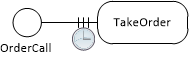
In OESjs, this can be coded by defining a class-level ("static") function waitingTimeout in a resource-constrained activity class, as shown in the following example. Typically, the timeout (or maximum waiting time) provided by such a function is sampled from a probability distribution function.
class TakeOrder extends aCTIVITY {
  constructor({id, startTime, duration}={}) {
    super({id, startTime, duration});
  }
  static duration() {
    return rand.uniform( 1, 4);
  }
  static waitingTimeout() {
    return rand.uniformInt( 3, 6);
  }
}
Section 3.2. Admissible Resources
When activities admit using more resources than required, this means they can be started as soon as the required number of resources are available, but they can also be started with a greater number of resources, typically implying a faster performance. This is illustrated in scenario 2 of the model Load-Haul-Dump-1, where two wheel loaders, instead of just one, can be allocated for performing a Load activity.
This is specified by the resource cardinality constraint 1..2 in the OE class model below for the Load-WheelLoader association at the WheelLoader side. The meaning of this resource cardinality constraint is that the activity type Load requires at least one wheel loader and allows up to two wheel loaders to be allocated for a Load activity.

Section 3.3. Organizational Positions and Resource Pools
Since a business process happens in the context of an organization (as its owner), it is natural to consider the concept of organizational positions.
Any performer role of an activity type has a performer type as its range. For instance, in the following OE class design model, the (implicitly named) performer role orderTaker of the activity type TakeOrder has the performer type OrderTaker as its range. Likewise the object type PizzaMaker is a performer type.
Each performer type corresponds to an organizational position. For instance, in the following OE class model, both OrderTaker and PizzaMaker are organizational positions, for which an organization hires a number of human resources, forming corresponding resource pools (called orderTakers and pizzaMakers). These resource pools correspond to the direct populations of the two organizational positions.

An organizational position may subsume more than one performer role. In the model above, the organizational position PizzaMaker is an alternative resource subtype of the organizational position OrderTaker, as indicated by the generalization arrow of category
Resource Pools Assigned to Multiple Activity Types
When a resource pool represents an organizational position charged with playing n performer roles, it is used by all n corresponding activity types.
Section 3.4. Alternate Resource Pools
Certain activities allow alternative resources, when no standard resources are available. For instance, in a pizza service company, when no order taker is available, and a new order call comes in, an available pizza baker can take the order. Or in a hospital, where nurses guide patients to an examination room, when no nurse is available, a receptionist can guide a patient to an examination room.
The general conceptual pattern is that for certain types of activities A (like GuideToRoom), a resource role r (like guide) may be played not only by instances of its direct resource type R (like Guide), but also by instances of an alternative resource type R' (like ExaminationAssistant) or an organizational position P (like Nurse), if they are a subtypes of R (Guide).
When the resource type R is not abstract, then its instances are the preferred resources of activities of type A, and its (possibly preference-rank-annotated) «ar» subtypes specify types of alternative resources.
Preferred and Alternate Resource Pools
Resource roles, resource types, organizational positions and resource pools are defined in an OE class design model. Each resource role has a resource type or an organizational position as its range and an assigned resource pool .
By default, for any non-abstract resource type R and for any organizational position P assigned as the range of a resource role r, an OE simulator can create a resource pool with the same (yet pluralized) name, pooling objects instantiating R or P, and assign it to r as the preferred resource pool.
Section 3.5. Task Priorities
Whenever an activity of type A1 ends and there is still another A1 task in the queue, the activity's resources would be re-used for the next A1 task unless there is another task (say, of type A2) with higher priority waiting for one of the resources (r1). In that case, r1 is allocated to that task, and all other resources are allocated to the next A1 task, which still has to wait for r1 becoming available again.
For example, in a pizza service, where incoming orders can be taken by pizza makers, and TakeOrder tasks have a higher priority than MakePizza tasks, when a MakePizza activity performed by a pizza maker in an oven ends while there is still another MakePizza task in the queue and there is also a TakeOrder task in the queue, the pizza maker is allocated to the TakeOrder task and the oven is allocated to the next MakePizza task, which has to wait for a pizza maker becoming available.
Algorithmically: Whenever an activity a1 of type A1 ends, collect all pairs <r, t> such that r is a resource used by a1 and t is the next task of an activity type A from the dependent activity types DAT of pool(r) with the highest priority among all DAT with task priorities higher than A1. For all these pairs <r, t>, allocate r to t. Allocate the remaining resources of a1 to the next A1 task, if there is any, otherwise release them.
Section 3.6. Task Preemption
Appendix A. Further Example Models
Section A.1. Make and Deliver Pizza

A pizza service company takes phone orders for making and delivering pizzas, with the help of order takers, pizza makers, ovens and a crew of pizza delivery scooter drivers. From time to time the order takers cannot cope with the number of incoming calls, and then customers grow impatient and hang up the phone without placing an order.
For getting a quick impression, you can run this model from the Sim4edu website, or inspect its OESjs code.
Since there is a high number of lost orders due to long waiting times in the first model, assigning different responsibilities to organizational roles for allowing a more flexible use of human resources is considered in a variant of the first model.
Our Make-and-Deliver-Pizza modeling problem is based on the chapter "Example Model 3: Pizzeria operation" in the book The Art of Process-Centric Modeling with AnyLogic by Arash Mahdavi.
Conceptual Model
A pizza service company has resource pools for order takers, pizza makers, pizza ovens, delivery staff and scooters. While take order activities are performed by an order taker, make pizza activities require both an oven and a pizza maker. Finally, deliver pizza activities require a delivery staff member and a scooter.
Conceptual Information Model
The potentially relevant object types are:
- pizza service company,
- customers,
- orders,
- pizzas,
- order takers,
- pizza makers,
- pizza ovens
- delivery scooter drivers,
- scooters.
Potentially relevant types of events and activities are:
- pizza ordering calls coming in from customers,
- order taking (an activity performed by order takers),
- customers hanging up the phone when having to wait for too long,
- pizza making (performed by pizza makers using ovens),
- pizza delivery (performed by delivery staff using scooters).
Object, event and activity types, together with their participation associations, can be visually described in a conceptual information model in the form of a special kind of UML class diagram, called Object Event (OE) class diagram, as shown below.

The association end annotations «rr» and «rp» denote resource roles and resource pools. For instance, the activity type make pizza has two resource roles, pizza makers and oven. A pizza service company has resource pools for order takers, pizza makers, ovens, delivery scooter drivers and scooters.
Resource roles have resource cardinality constraints. For instance, a make pizza activity requires 2 pizza makers and 1 oven.
A conceptual OE class diagram like the one above, describes resource roles (like oven), resource role types (like ovens) and resource cardinality constraints (like "exactly 1") for all types of activities.
An organization defines organizational positions, which are filled by human resources. Each organizational position is characterized by a set of human resource roles to be played by position holders. In the Pizza Service organization, there are three positions: order takers, pizza makers and delivery scooter drivers.
Strictly speaking, order phone calls are instantaneous (zero duration) events while a take order activity is an event with a non-zero duration. For simplicity, though, we'll often say "events" instead of "instantaneous events" or "objects, events and activities" instead of "objects, instantaneous events and activities".
Conceptual Process Model
The following BPMN diagram shows a conceptual process model of the Make-and-Deliver-Pizza business process, with three swimlanes for the three performers of the process:

Notice the BPMN Boundary Timeout Event circle attached to the take order activity representing timeout events that cancel the activity. They are supposed to model the reneging behavior of waiting customers loosing their patience and hanging up the phone without placing an order. However, BPMN does not allow restricting such a timeout mechanism to the waiting phase of a planned activity, that is the time span during which the planned activity has been enqueued, but not yet started. Rather, it applies to the entire cycle time of take order activities, which means that also started activities, where the order taker is already listening to the customer, may be canceled due to reneging.
While BPMN allows modeling the performers of activities with swimlanes, it does not support modeling other types of resource objects. As a workaround, we have included the resource objects ovens and scooters in the form of BPMN Data Objects.
The third, and most severe, issue of the BPMN model is its uniform (semantically overloaded) use of "sequence flow" arrows for sequencing events and activities. While in the case of all three activities, incoming "sequence flow" arrows do not mean that an activity is started, but rather that a new planned activity is enqueued (and only started when all required resources become available), in the case of the event lost order, the incoming "sequence flow" arrow means that a new event is scheduled to occur immediately.
These three issues of BPMN have been solved in DPMN, where resource-dependent activity scheduling (RDAS) arrows are distinguished from event scheduling arrows, as shown in the following DPMN process diagram:

Notice how the timeout event circle (with a clock icon) is attached to the three bars of the RDAS arrow representing the queue of planned order taking activities waiting for the availability of an order taker. This implies that the timeout applies to the waiting phase only, and not to the entire order taking activity.
A conceptual DPMN process diagram does normally not include any element representing a resource pool. Yet, it may display the performer roles of activity types, like order taker and pizza maker in the diagram above. It is assumed that for any organizational position described in the underlying OE class model, the organization under consideration has a corresponding resource pool.
Simulation Design
In our simulation design, we make the following simplifications. We consider only one particular pizza service company, which does not have to be modeled as an explicit object. Also, we abstract away from individual customers, orders and pizzas. And we merge the resource roles delivery scooter driver and scooter, keeping only scooters as resources of deliver pizza activities.
We consider a scenario with two order takers, ten pizza makers, five ovens and 20 scooters.
Information Design Model
An information design model, in the form of an OE class diagram as shown below, is derived from a conceptual information model by
- Abstracting away from items that are not design-relevant.
- Adding properties, functions and methods to object, event and activity classes. In particular, a status attribute is added to all resource object types, such as OrderTaker and Oven, and a class-level duration function is added to all activity classes.

Notice how functions representing random variables, like the duration function of all activity types, are marked with the keyword (or UML 'stereotype') «rv» standing for "random variable". These random variable functions sample from a probability distribution function (PDF), which is symbolically indicated with expressions like Tri(30,40,50) standing for the triangular PDF with lower and upper bounds 30 and 50 and a median of 40, or DU(1,4) standing for the discrete uniform PDF with lower and upper bounds 3 and 6.
In the case of the event type OrderCall, the random variable function recurrence samples from an exponential PDF with five different event rates given for the five consecutive hours during which the pizza service operates.
The activity type TakeOrder is associated with the object type OrderTaker via the implicit resource role orderTaker (with a resource cardinality constraint of "exactly 1"), indicated with the association end stereotype «rr» standing for "resource role". A resource role assigns resource objects to activities.
Likewise, MakePizza is associated with PizzaMaker and Oven via the (implicitly named) resource roles pizzaMakers, having a resource cardinality constraint of "exactly 2", and oven, having a resource cardinality constraint of "exactly 1".
An OE class design diagram like the one above, defines resource roles (like pizzaMakers), resource role types (like PizzaMaker) and resource cardinality constraints (like "exactly 2") for all types of activities. Normally, in an OE simulation there is a one-to-one correspondence between resource role types and resource pools. By convention, a resource pool has the same name as the corresponding resource role type, yet pluralized and starting with a lowercase character. For instance, the name of the resource pool for PizzaMaker is pizzaMakers.
Notice that OrderCall events are exogenous, having a recurrence function defined case-wise for each of the five hours per day operation of the pizza service company (in the attached invariant box).
For implementing the waiting timeout event defined in the process model, the activity type TakeOrder has a class-level waitingTimeout function implementing a random variable with PDF U(3,6).
Process Design Model
A process design model, in the form of a DPMN process diagram as shown below, is derived from a conceptual process model by abstracting away from items that are not design-relevant and possibly adding certain computational details.
A DPMN process design model (like the one shown in Figure A-2) essentially defines the admissible sequences of events and activities together with their dependencies and effects on objects, while its underlying OE class design model (like the one shown in Figure A-1) defines the types of objects, events and activities, together with the participation of objects in events and activities, including the resource roles of activities, as well as resource cardinality constraints, parallel participation constraints, alternative resources, and task priorities.

It is an option, though, to enrich a DPMN process design model by displaying more computational details, especially the recurrence of exogenous events, the duration of activities and the most important resource management features defined in the underlying OE class design model, such as resource roles (in particular, performer roles can be displayed in the form of Lanes) and resource cardinality constraints. The following model shows an enriched version of Figure A-2:

Such an enriched DPMN process design model includes all computational details needed for an implementation without a separate explicit OE class design model. In fact, such a process model implicitly defines a corresponding class model. For instance, the enriched DPMN model of Figure A-3 implicitly defines the OE class model of Figure A-1 above.
The notation for defining performer roles in Lanes consists of a performer role name (such as pizzaMakers) and and an object type name (such as PizzaMaker) denoting its range, separated by a colon. When the performer role name is appended by a multiplicity expression in brackets, as in pizzaMakers[2], this denotes a resource cardinality constraint (stating that exactly 2 pizzaMakers are required). When only a performer type prefixed with a colon (such as :OrderTaker) is provided, this means that the implicit performer role name is obtained by lowercasing the performer type name (as in orderTaker:OrderTaker).
The notation for defining a non-performer resource role, such as oven:Oven, consists of a named object rectangle, such as the :Oven rectangle in Figure A-3, attached to an activity rectangle by means of a connection line with a small filled square representing a resource link, such as the line between the MakePizza activity rectangle and the :Oven object rectangle in Figure A-3.Notice that the model of Figure A-3 does not include any element representing a resource pool. It is assumed that for any organizational position described in the underlying OE class model, the organization under consideration has a corresponding resource pool. By default, each resource role of an activity type is associated with a resource pool having the same (yet pluralized) name, such that its resource objects are instances of a corresponding resource role type, which is an organizational position in the case of human resources.
For instance, for the MakePizza activity a pool ovens is assigned to its resource role oven by default. The members of the pool ovens are instances of the (resource) object type Oven. Likewise, a pool pizzaMakers is assigned to the MakePizza resource role pizzaMaker. The members of this pool are instances of the organizational position PizzaMaker. These default pool assignments are normally not shown in a DPMN diagram, but an OE simulator takes care of them.
Combined with its underlying OE class design model, a DPMN process design model provides a computationally complete specification of a simulation model that can be directly turned into implementations.
Model Variant: Orders May Also Be Taken by Pizza Makers
For decreasing the number of lost orders due to long waiting times, it is advisable to charge pizza makers with taking orders whenever no order taker is available. In resource management terminology, the organizational position pizza maker is redefined by adding the performer role order taker to its portfolio of organizational roles.
In an OE class diagram, this can be expressed by adding a subtyping arrow from pizza makers to order takers categorized as an alternative resource subtyping arrow with the stereotype «ar», as shown in the following diagram:
The DPMN process model is not affected by this change.
Section A.1.1. Implementation with OESjs
The JavaScript-based simulator OESjs-Core2 implements the Object Event Simulation (OES) paradigm, and, consequently, allows a straight-forward coding of OE class models and DPMN process models.
Implementing the Information Design Model
For implementing the OE class design model with OESjs-Core2, we have to code all object types, event types and activity types specified in the model in the form of JavaScript classes extending the respective OESjs framework classes oBJECT, eVENT and aCTIVITY. We start with the object type OrderTaker shown in the following diagram:

The OrderTaker object class can be coded in the following way:
class OrderTaker extends oBJECT {
  constructor({ id, name, status}) {
    super( id, name);
    this.status = status;
  }
}
All object classes inherit an id attribute and a name attribute from the pre-defined OES foundation class oBJECT. Since order takers are resource objects, we need to define a status property having the pre-defined enumeration data type ResourceStatusEL as its range.
The other object classes (PizzaMaker, Oven and Scooter) are coded in the same way.
We next show how to code the event type OrderCall depicted in the following diagram:

The OrderCall event class is coded in the following way:
class OrderCall extends eVENT {
  constructor({ occTime, delay}) {
    super({occTime, delay});
  }
  createNextEvent() {
    return new OrderCall({delay: OrderCall.recurrence()});
  }
  static recurrence() {
    var hour = Math.floor(sim.time / 60);
    return rand.exponential( OrderCall.arrivalRates[hour]);
  }
}
// arrival rates per minute (for a daily operation for 5 hours)
OrderCall.arrivalRates = [1/6, 1/0.66, 1/1.5, 1/6, 1/12];
All event classes inherit an occTime attribute and a delay attribute from the pre-defined OES foundation class eVENT. Any event in OES can be created either with a value for the attribute occTime (standing for occurrence time) or with a value for the attribute delay. In the latter case, the event's occurrence time is automatically derived by adding the value of delay to the current simulation time.
Notice how the time-varying recurrence rates (representing order arrival rates) are implemented in the recurrence function: by first computing the current hour, which is then used as an index for accessing the corresponding element of the OrderCall.arrivalRates array.
Finally, we show how to code the activity type TakeOrder depicted in the following diagram:

The TakeOrder activity class is coded in the following way:
class TakeOrder extends aCTIVITY {
  constructor({id, startTime, duration}={}) {
    super({id, startTime, duration});
  }
  static duration() {
    return rand.uniform( 1, 4);
  }
  static waitingTimeout() {
    return rand.uniformInt( 3, 6);
  }
}
TakeOrder.resourceRoles = {
  "orderTaker": {range: OrderTaker}
}
All activity classes inherit the attributes id, startTime and duration from the pre-defined OES foundation class aCTIVITY. When an activity is created as a JS object during a simulation run, the value of its duration property is obtained by invoking the duration() function defined as a class-level ("static") function for its activity class. These activity duration functions typically implement a random variable by invoking a random variate sampling function, such as rand.triangular(30,50,40), which samples from the triangular probability distribution function (with min/max=30/50 and mode=40).
Notice how the resource role association between TakeOrder and OrderTaker, which defines the resource reference property TakeOrder::orderTaker, is coded by a corresponding entry in the map-valued class-level property resourceRoles.
Implementing the Process Design Model
The following process design model specifies six types of events: order call events, take order waiting timeouts, lost order events, take order activities, make pizza activities, and deliver pizza activities:
A DPMN process design model can be decomposed into a set of event rule design models, one for each type of event specified in the design model. Since the LostOrder event and the DeliverPizza activity do not have any effects, we only need four event rules.
1 The OrderCall event rule
Starting with the following OrderCall event rule design model, we show how the event rules specified by each of these event rule design models can be coded.

The OrderCall event rule does not define any state changes of affected objects, but only the resource-dependent scheduling of a TakeOrder activity, which is coded with the following OESjs statement:
OrderCall.successorActivity = "TakeOrder";
2 The TakeOrder Waiting Timeout event rule

The TakeOrder Waiting Timeout event rule only schedules the immediate occurrence of a LostOrder event, which is coded with the following OESjs event routine within the TakeOrder activity class:
onWaitingTimeout() {
  var followupEvents=[];
  followupEvents.push( new LostOrder());
  return followupEvents;
}
3 The TakeOrder event rule
Since activities are composite events, we also have event rules for them. These rules are triggered when an activity completes, that is, by the corresponding activity end events.

The TakeOrder event rule only takes care of the resource-dependent scheduling of a MakePizza activity, which is coded with the following OESjs statement:
TakeOrder.successorActivity = "MakePizza";
4 The MakePizza event rule

The MakePizza event rule only takes care of the resource-dependent scheduling of a DeliverPizza activity, which is coded with the following OESjs statement:
MakePizza.successorActivity = "DeliverPizza";
You can run this model from the OES GitHub website, or inspect its OESjs code.
Section A.2. Load-Haul-Dump

A haul service company accepts requests for hauling large quantities of earth from a loading site to a dump site, using dump trucks and wheel loaders.
You can run this model from the Sim4edu website, or inspect its OESjs code.
Our Load-Haul-Dump modeling problem is based on the chapter "Example Model 2: Earthmoving operation" in the book The Art of Process-Centric Modeling with AnyLogic by Arash Mahdavi.
Conceptual Model
A haul service company has resource pools for dump trucks and wheel loaders. While the activities go (back) to loading site, haul, dump and go home just require a truck (or a wheel loader) as a resource, load activities require both a truck and a wheel loader.
Conceptual Information Model
The potentially relevant object types are:
- haul service company,
- wheel loaders,
- dump trucks.
Potentially relevant types of events and activities are:
- haul requests coming in from customers,
- going to the loading site (an activity performed by trucks and by wheel loaders),
- loading (performed by wheel loaders using trucks as resources),
- hauling (performed by trucks),
- dumping (performed by trucks),
- going back to loading site (performed by trucks),
- going home when the job is done (performed by trucks and by wheel loaders).
Both object types and event types, together with their participation associations, can be visually described in a conceptual information model in the form of a special kind of UML class diagram, called Object Event (OE) class diagram, as shown below.

Notice that the association end annotations «rr» and «rp» denote resource roles and resource pools. A haul service company has resource pools for trucks and wheel loaders. The activity types haul, dump and go back to loading site have a resource role truck for assigning a truck to any activity of one of those types. The activity types go to loading site and go home have either a a resource role truck or a resource role wheel loader, as indicated by the alternative association constraint expressed with a dashed line annotated with {xor}. The activity type load has both resource role truck and a resource role wheel loaders for assigning at least one and at most two wheel loaders to any load activity (as indicated by the multiplicity "1..2" at the «rr» association end at the class wheel loaders).
Conceptual Process Model
The involved types of events and activities can be related with each other via resource-dependent activity scheduling arrows and event scheduling arrows, as shown in the following DPMN process diagram:

Notice that there are three types of arrows in this DPMN diagram:
- Event Scheduling arrows, like the one between load and haul, have the meaning that the succeeding activity is started as soon as the preceding activity has been completed (there is no need for enqueuing a planned activity, since all resources required by the succeeding activity are provided by the preceding activity). Event Scheduling arrows are not part of BPMN, rather they have been proposed by Schruben (1983) for Event Graphs.
- A Multiple Events Scheduling arrow, like the one between requests and go to loading site, means that one instance of the preceding event type triggers multiple instances of the succeeding event type. In our example model, this means that one request event is followed by multiple go to loading site activities, one for each truck and each wheel loader assigned to the job.
- A Resource-Dependent Activity Scheduling arrow, like the one between go to loading site and load activities, means that as soon as an activity of the preceding activity type has been completed, a new planned activity is added to the queue of planned activities of the succeeding type (and started as soon as all required resources are available).
The model shows that when a haul request comes in, the haul service company deploys multiple trucks and wheel loaders to the loading site, each of them performing a go to loading site activity, as indicated by the double arrow between the haul requests event circle and the go to loading site activity rectangle. Each of these activities leads to enqueuing a new planned load activity, as indicated by the resource-dependent activity scheduling arrow from the go to loading site activity shape to the load activity shape. Such an enqueued (planned) activity is going to be dequeued and started as soon as the required resources become available. This means that as soon as a wheel loader is available, the next load activity is going to be started. When a load activity is completed, a haul activity and then a dump activity are going to start immediately, as indicated by the event scheduling arrows between them.
A more complete model prevents trucks to go back to the loading site and perform a load activity even when the job has been completed during the go back activity (resulting in haul and dump activities with an empty truck). For avoiding this uneconomic behavior, a second decision if the job has been done needs to be taken after the go back activity. In addition, the model has to describe that wheel loaders also go home when their job has been done. This is shown in the following refined model:

Simulation Design
In our simulation design, we consider only one particular haul service company, which does not have to be modeled as an explicit object. Also, we abstract away from the fact that also wheel loaders have to go to, and return from, the loading site by assuming that they are already at the site when the dump trucks arrive.
Information Design Model
In the information design model, we need to define a status attribute for all resource object types, such as Truck and WheelLoader, and a duration function, typically representing a random variable, for each activity type:
Notice how functions representing random variables, like the duration function of all activity types, are marked with the keyword (or UML 'stereotype') «rv» standing for "random variable". These random variable functions sample from a probability distribution function (PDF), which is symbolically indicated with expressions like Tri(30,50,40) standing for the triangular PDF with lower and upper bounds 30 and 50, and a median of 40.
Each activity type is associated with Truck or WheelLoader as their resource role(s), indicated with the association end stereotype «rr» standing for "resource role".
Process Design Model
A process design model, in the form of a DPMN process diagram as shown below, is derived from a conceptual process model by
- Abstracting away from items that are not design-relevant.
- Defining event variables, if needed.
- Defining object variables in the form of Data Object boxes for specifying state changes of objects affected by events.
- Formalizing decision conditions on the basis of event and object variables.

Section A.2.1. Implementation with OESjs
The JavaScript-based simulator OESjs implements the Object Event Simulation paradigm, and, consequently, allows a straight-forward coding of OE class models and DPMN process models.
Implementing the Information Design Model
For implementing the OE class design model with OESjs, we have to code all object types, event types and activity types specified in the model in the form of JavaScript classes.

The Truck object class can be coded with OESjs-Core2 in the following way:
class Truck extends oBJECT {
  constructor({ id, name, status}) {
    super( id, name);  // invoke the oBJECT constructor
    this.status = status;
  }
}
// a class-level attribute
Truck.capacity = 15;  // m3
All object classes inherit an id attribute and a name attribute from the pre-defined OES foundation class oBJECT. Since trucks are resource objects, we need to define a status property for them. We also define a class-level attribute capacity for modeling their load capacity, assuming that all trucks have the same capacity.
The WheelLoader object class is coded in the same way as Truck.

The HaulRequest event class can be coded in the following way:
class HaulRequest extends eVENT {
  constructor({ occTime, delay, quantity}) {
    super({occTime, delay});
    this.quantity = quantity;
  }
  onEvent() {
    ...
  }
}
All event classes inherit an occTime attribute and a delay attribute from the pre-defined OES foundation class eVENT. Any event in OES can be created either with a value for the attribute occTime (standing for occurrence time) or with a value for the attribute delay. In the latter case, the event's occurrence time is automatically derived by adding the value of delay to the current simulation time. In addition, the HaulRequest event class has a property quantity for specifying the quantity to be hauled.
The onEvent method of the HaulRequest event class is not part of the information design model. Rather, it is implementing an event rule specified in the process design model. Consequently, it will be discussed below.

The GoToLoadingSite activity class can be coded in the following way:
class GoToLoadingSite extends aCTIVITY {
  constructor({id, startTime, duration}={}) {
    super({id, startTime, duration});
  }
  static duration() {return rand.triangular( 30, 50, 40);}
}
GoToLoadingSite.resourceRoles = {
  "truck": {range: Truck}
}
All activity classes inherit the attributes id, startTime and duration from the pre-defined OES foundation class aCTIVITY. When an activity is created as a JS object during a simulation run, the value of its duration property is obtained by invoking the duration() function defined as a class-level ("static") function for its activity class. These activity duration functions typically implement a random variable by invoking a random variate sampling function, such as rand.triangular(30,50,40), which samples from the triangular probability distribution function (with min/max=30/50 and mode=40).
Notice how the resource role association between GoToLoadingSite and Truck, which defines the resource reference property GoToLoadingSite::truck, is coded by a corresponding entry in the map-valued class-level property resourceRoles.
Implementing the Process Design Model
A DPMN process design model can be decomposed into a set of event rule design models, one for each type of event specified in the design model. Starting with the HaulRequest event rule design model, we show how the event rules specified by each of these event rule design models can be coded in the form of an onEvent method.
HaulRequest event rule.
In the following HaulRequest event rule method onEvent, all available trucks are allocated to the current haul request, and, after computing the number of loads, for each of the allocated trucks a new GoToLoadingSite activity is started:
class HaulRequest extends eVENT {
  ...
  onEvent() {
    const followupEvents=[],
          allocatedTrucks = sim.resourcePools["trucks"].allocateAll();
    // assign model variable
    sim.model.v.nmrOfLoads = Math.ceil( this.quantity / Truck.capacity);
    for (const t of allocatedTrucks) {
      const goActy = new GoToLoadingSite();
      // assign truck as required resource
      goActy.truck = t;
      // start GoToLoadingSite activity
      followupEvents.push( new aCTIVITYsTART({plannedActivity: goActy}));
    }
    return followupEvents;
  }
}
Since activities are composite events, we also have event rules for them. The following GoToLoadingSite event rule is triggered whenever a GoToLoadingSite activity is completed, since the completion of an activity counts as its occurrence event.
GoToLoadingSite event rule.
This rule states that whenever a GoToLoadingSite activity ends (or is completed), then a new planned Load activity is enqueued, if no wheel loader is available, or, otherwise, a new Load activity is started. In OESjs, it is coded in the following declarative way:
GoToLoadingSite.successorActivity = "Load"
Such a successor activity assignment allows the simulator to check if the required resources are available and then start the successor activity, or, otherwise, enqueue a new planned successor activity.
Load event rule.
This rule states that whenever a Load activity ends, the model variable nmrOfLoads is decremented by 1, and a Haul activity is immediately started (as a successor activity). Since the Haul activity doesn't require any additional resources, there is no need to enqueue a planned activity and wait for the availability of resources. In OESjs, this rule is coded in the following way:
class Load extends aCTIVITY {
  ...
  onActivityEnd() {
    const followupEvents = [];
    // decrement nmrOfLoads counter
    sim.model.v.nmrOfLoads--;
    return followupEvents;
  }
  ...
}
Load.successorActivity = "Haul";
Notice that the state change expressed in the modelVariables object rectangle, the decrementation of nmrOfLoads, is taken care of in the onActivityEnd method of the Load activity class. Instead of explicitly scheduling the start of the succeeding Haul activity in that method, we simply define Haul to be the successor activity of Load.
Haul event rule.
The Haul event rule states that whenever a Haul activity ends, it is immediately succeeded by a Dump activity. It is coded in the following way:
Haul.successorActivity = "Dump";
Dump event rule.
The Dump event rule states that when a Dump activity ends and the model variable nmrOfLoads has the value 0, it is immediately succeeded by a GoHome activity, otherwise it is immediately succeeded by a GoBackToLoadingSite activity. The rule is coded by defining the successor activity as a function returning either "GoBackToLoadingSite" or "GoHome" in the following way:
Dump.successorActivity = function () {
  return sim.model.v.nmrOfLoads === 0 ? "GoHome":"GoBackToLoadingSite";
}GoBackToLoadingSite event rule.
The GoBackToLoadingSite event rule states that when a GoBackToLoadingSite activity ends and the model variable nmrOfLoads still has a value greater than 0, a new planned Load activity is enqueued; otherwise a GoHome activity is immediately started. The rule is coded by defining the successor activity of GoBackToLoadingSite as a function returning either "Load" or "GoHome" in the following way:
GoBackToLoadingSite.successorActivity = function () {
  return sim.model.v.nmrOfLoads > 0 ? "Load":"GoHome";
}
Appendix B. Simulator Architecture
OES Core 2 adds the following features to OES Core 1:
- activities as composite events, having a start event and an end event, and a duration as the time in-between their start and end events
- resource roles with resource cardinality constraints
- resource pools (supported in two forms: count pools and individual pools)
- automated (a) throughput, (b) queue length, (c) waiting time, (d) cycle/throughput time, and (e) resource utilization statistics per activity type
The OES Core 2 simulator's information architecture is described by the following class diagram:
